This page documents the Cold War infrastructure of the UK state telecommunications operator, the G.P.O. a Government Ministry in the fifties, that became a nationalised industry, P.O. Telephones in the late sixties. Then privatised in the eighties as British Telecom.
The Need for a Resilient Communications Network
With WWII accord behind us, the fifties saw tensions increasing between East and West in the Cold War, the GPO made a multi-prong approach to improving the resilience of communications in the UK. At the same time there was a large growth in the use of the telephone and many military projects requiring telecommunications services.
Modernisation of the network was underway in the fifties, replacing manual operator switchboards with automatic Strowger type telephone exchanges, to handle long distance telephone calls. This project known as 'Trunk Mechanisation' was also design to move the switching away from London into provincial 'Zone' centres.
City centres were vulnerable to bombing, three deep level exchanges were built in Birmingham, London and Manchester able to withstand a Hiroshima size nuclear weapon. These and other cities such as Bristol had what was called 'Ring' schemes, diverting long distance telephone cables away from the centre and around the outskirts of the city. Some of these rings had specially hardened semi-underground repeater stations, but hardly enough were built to be effective, before the policy changed.
Another proposal was to provide a 'Backbone' microwave radio network as a backup to long distance cables. Specially hardened radio equipment rooms were to be built at these backbone sites. In the event, the demand for long distance television circuits took precedence, so it was many years later before it was implemented, but without the originally planned hardened buildings.
Change of Plans
The Soviet Union surprised the Western Allies by testing a Hydrogen Bomb on November 22, 1955 with a yield of about 1.6 Megatons, about 80 times more powerful than the Hiroshima bomb. This required a major rethink of policy towards hardened and underground buildings, resulting in Manchester being the last underground exchange and no further hardened repeater stations.
Cabinet Office File CAB134/2135 in the National Archives at Kew, dated 26th August 1958, states that the Post Office plans were based on the 1955 Strath Committee Report. This assumed that the U.K. would be faced with an attack by Nuclear Weapons on 10-15 major centres of population.
CAB134/2135 goes on to say that later information, presented in document C.D.(58)2 states it must be assumed this country would be faced with attack on 40-50 bomber and rocket bases as first priority targets, but that, in addition some centres of population would remain as secondary targets. . . .
It draws the conclusion With more than 40-50 targets for nuclear weapons, some of which will change from time to time and all will be subject to the inaccuracy of bomb or rocket, no part of the country could be regarded as safe. While some parts of the country are safer than others, it would seem to be essential not to put a high proportion of our eggs in one heavily protected and expensive basket - the Backbone system - particularly as parts of that system are only 10 miles from probable targets.
The document goes on to suggest 4 principles by which the plans should be modified. (1) A start should be made at providing some fallout protection at key centres. (2) Expensive precautions against damage on any route should be dropped. (3) Vital circuits should be given alternative routes as widely dispersed geographically as possible. (4) For financial reasons as much use as possible should be made of existing and projected civil radio stations and cable routes.
Chronology of Work
Annual Reports made by the GPO Engineer in Chief (E-i-C) shed light on the developments of the network and resilience schemes, but often lack the detail to be certain as to what they are referring to. The blue italic text from these annual reports are sourced from the BT Archives.
E-i-C Report 50-51
Page 56: Two standard buildings of a specialized character have been designed to give a high degree of protection to equipment housed therein from blast and external fire hazard. They will have gross superficial floor areas of approximately 19,000 and 22,000 sq. ft. The buildings, which are known as Types PR1 and PR2, differ only in the length of the apparatus rooms; they are semi buried and of windowless monolithic reinforced concrete construction. The report goes on to describe features of the air conditioning.
E-i-C Report 51-52
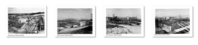
Page 62: Although some interior details of the PR1 and PR2 buildings, described in the last Report (page 56), have yet to be finally settled, the building of a number of each type has started. Plate 7 on Page 108 shows one under construction. . . That photograph and those mentioned in the next annual report are reproduced in the PR1 Construction gallery below.
E-i-C Report 52-53
Page 44: During 1952/53, contracts placed for defence works, including Rotor and Infrastructure, totalled £1.41m. and preponderated over those placed for development of the normal trunk network, which amounted to £1.05m. In addition, instructions were issued to Regions for the installation by direct labour, of audio equipment for 45 Rotor and defence stations and 87 normal works, and for 74 music amplifier installations including nine for the B.B.C. emergency scheme. . . The ROTOR radar project built 31 massive underground bunkers and 6 surface radar stations. Working to 6 Sector operations centres 4 of which were newly built underground bunkers.
Page 45: Contracts have been placed for the initial equipment requirements of the Birmingham and Bristol Provincial Ring Scheme. . . . . . . During 1952/53, contacts were placed for the installation of repeater station power plant to a total estimated value of £325,000. This is less than half the value of plant ordered during 1951/52 (£777,000) because, that year, an abnormal proportion of large plants for the new stations in the Provincial Ring Schemes was ordered.
In this year, the BT Archives contain a number of photographs of the construction of London Kingsway exchange dated 30 January 1952 (TCB417/E17648 to E17671) - See the next topic on this page
Page 67: Almost all the year's work was expended on the provision of buildings for defence schemes, including Rotor.
Seven new R5-type terminal repeater station buildings were completed, one being a Rotor requirement and the other six forming parts of the London and Provincial Ring Schemes.
Twenty-one intermediate carrier station buildings have been completed, all for carrier ring and 24-circuit conversion schemes required for Rotor and defence. Nine of the buildings are of the R4-type with accommodation for a small number of carrier terminals. These are situated at selected points where circuits may need to be extracted to feed Services installations, and terminal equipment is already being provided in one of the stations for this purpose. Eight of the remaining 12 buildings are of the R3-type to house pre-51-type carrier line equipment, and the final four are the first R3 A.C.-type buildings to be provided and will be used for the first route to have 51-type carrier line amplifiers (Edinburgh - Dundee).
Accommodation for Rotor and defence schemes, which was required too urgently to permit the erection of permanent buildings, has been provided in nine wooden huts. Seven of the huts will house transmission equipment, and two will contain power plant. They will serve as temporary repeater stations until permanent buildings can be made available. The huts, known from the manufacturer's name as "Bath" huts, are provided by the Ministry of Works and are constructed in sections 6 feet long and 20 feet wide, with a clear height of 12 feet. As delivered by the manufacturer, the huts are not lined but the contract for erection includes lining with foil-backed plaster board. As the huts would not be strong enough to withstand the lateral stresses imposed if the normal practice of tying transmission equipment racks to angle irons on the walls were adopted, Steel channels 3 in. x 1½ in., set in the concrete base, are erected vertically at intervals along the walls and used to support the horizontal 2 in. x 2 in. angle iron to which the rack tie-bars and cable rack and busbar supports are fixed.
The construction of a number of the PRl and PR2 buildings, referred to in the 1951/52 Report (page 62) has now reached an advanced stage. A building is illustrated in Plate 12, Figs. 2 and 3. The main part of this building is approximately 190 feet long by 50 feet wide and protrudes about 14 feet above ground level. Drying out those large concrete structures, particularly during the wet weather of the past year, has proved to be a bigger problem than had been anticipated. One Region overcame this problem very successfully by using an agricultural grain dryer, and arrangements have been made for other Regions to employ this method where they find it necessary.
. . . . Major building extensions at five terminal repeater stations and extensions of four temporary stations have been completed. . . . . .Much work has been done on the planning and allocation of accommodation in basements of buildings for which special protective measures are to be provided.
E-i-C Report 53-54
Page 17: Special measures have been taken to provide security for trunk communications throughout the country. Schemes have been prepared for giving protection to trunk switching equipment and telephone repeater equipment, and the use of several different cable routes for the groups of trunk circuits between main centres has minimised the general effect of any interruption on individual trunk cables. Note: Trunk = Long Distance
Page 40: Reorganisation of the Control and Reporting System continued throughout the year. Cabling for 25 new stations has been planned and 17 of these are completed; the remainder are proceeding satisfactorily. Rearrangement and provision of a large number of private circuits, in preparation for the opening of these new stations, was put in hand and, for four of the 25 completed. . . . The requirements of an additional 13 stations for a later stage of the Control and Reporting System have been advised by the Air Ministry and preliminary planning has actively pursued. Control and Reporting sounds like part of the ROTOR plan.
Page 52: In connexion with the ring schemes, equipment has been ordered for the diversion of the following carrier cables. Bristol - Salisbury, Patchway - Warmley, Bristol - Oxford, Felton - Warmley, Lyndon - Queslett, Selly Oak - Queslett, Selly Oak - Lyndon, Bristol - Gloucester, Oldham - Swinton, Stockport - Swinton, Oldham - Stockport, Moortown - Rothwell Haigh, Gildersome - Moortown.
Those familiar with hardened repeater stations will recognise Lyndon and Queslett (Birmingham ring), Warmley (Bristol ring,) Swinton and Stockport (Manchester ring), Uddingston (Glasgow ring) and Rothwell Haigh (Leeds ring). On Page 72, there is a report of the completion of 6 PR1 and 1 PR2 type of protected repeater buildings.
E-i-C Report 54-55
Page 13: During the year, the final stages in the present trunk mechanisation plans for London were completed with the opening of London Trunk Kingsway and the incoming section of London Trunk Faraday on 30 October 1954 and 8 January 1955 respectively. Note: Kingsway is the underground exchange. Also during this year, the Speaking Clock rolled out to 34 centres outside the major cities, to play its part 10 years later as the bearer for HANDEL.
Page 40: The first stage of the Control and Reporting System has continued throughout the year and cabling has been completed. Rearrangement and provision of a large number of private wires has resulted in 19 stations being prepared for service. The Air Ministry has opened 17 of these and decided to abandon two. Abandoning these two stations at Calvo and Charmy Down marks the demise of ROTOR plan. Some of the redundant bunkers were reused as Regional Government HQs.
Page 41: At the end of 1954 it became known that the A.A. requirements were totally reorganised, which would mean the cessation of most of the A.A. network. . . . . Instructions to cease some 600 circuits were received. This refers to the stand down of the Anti Aircraft (A.A.) batteries in the Gun Defended Areas (GDA) and the A.A. Operations Rooms (A.A.O.R.). Many AAOR were reused for other purposes, Lansdown -> ROC Sector HQ, Ullenwood -> RGHQ 7.1 and others became Local Authority Emergency Centres, like Mistley, Essex.
Glasgow Ring Scheme Page 54: The Glasgow - Oban coaxial route will terminate at the new Glasgow / Uddingston repeater station, and 24 circuit carrier line amplifier equipment has been ordered for this station to enable the existing Glasgow - Perth - Dundee and Carlisle - Glasgow routes to be be intercepted. This will associate the new Uddingston station with the main carrier network. There is a reference to another new repeater station at Kirkintillock. This was in Washington Rd G66 1DP but appears to have been demolished and replaced by flats, so its not known if it were a protected repeater PR building.
Further down the page: The Margaretting - Tunbridge Wells carrier route will complete a new carrier ring cable system on the South side of London, interconnecting at Guildford with the Northern carrier ring previously provided and at Margaretting with the existing London - Norwich carrier route.
E-i-C Report 55-56
Page 58: Reports that carrier equipment was ordered for a number of routes and these include Anchor - Queslett and Anchor - Lyndon. Anchor being the Birmingham underground exchange, Queslett and Lyndon are two protected repeaters on the Birmingham Ring Scheme.
E-i-C Report 58-59
Page 35: In addition, 24-circuit or 60-circuit line amplifying equipment will be provided for the following cables. The fourth line Woodland - Cheltenham - Shrewsbury (60-circuit carrier cable) Woodland exchange is located at the Central Government War HQ in Corsham quarries.
Page 65: The installation of standby generating plant at the Birmingham Anchor and Manchester Guardian schemes has been completed. Each installation consists of three three-cylinder two stroke oil engines each developing 400 b.h.p. at 600 rev/min and directly coupled to 300 kVa alternators.
Secret Underground Exchanges
Three underground exchanges were built in the nineteen fifties that were classified secret until the mid sixties. These were designed to withstand a Hiroshima type blast but as atomic weapons became more powerful they were rendered useless. The exchanges were used until the early eighties but now only the cable infrastructure remains. To preserve their anonymity during their construction, Birmingham Anchor was known as 'Tunnel Scheme 526', London Kingsway as 'Tunnel Scheme 2147' and Manchester Guardian as 'Tunnel Scheme 567'. Authority for the work was granted to the Post Master General by the 'Post Office Works Act 1959'. Hansard on 21-Oct-1968 mentions that a fourth exchange at Glasgow was abandoned after the initial bore holes were made. The three exchanges were declassified in the mid-sixties, although there have been numerous newspaper articles and books exposing their presence, they never attracted the attention of the general public, who were more interested in the sighting of poles and telephone kiosks.
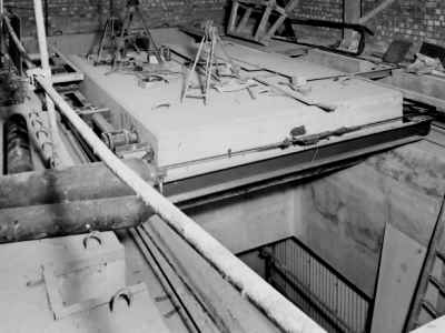
The main point of vulnerability for the underground exchange is the surface building. To protect the access shafts they were fitted with large sliding concrete slabs, having hydraulic rams to close and open them afterwards even if the containing building had collapsed. The image below shows the installation of a cap on one of Guardian's shafts.
Sliding Concrete Shaft Slab
Birmingham Anchor is named after the hallmark used by the Birmingham Assay Office, in those days situated close to the tunnel complex. Manchester Guardian exchange is named after the 'Manchester Guardian' daily newspaper, although it dropped 'Manchester' from its title in 1959 and continues today as 'The Guardian'. The little known exchange came to the public notice on 29 March 2004 when a fire in the cable network severely disrupted the telephone network around the Manchester area for a number of days. London Kingsway exchange is named after a main thoroughfare less than 500 metres west of the tunnel complex.
Birmingham Anchor Exchange
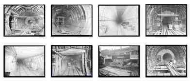
Birmingham Anchor Exchange (BM/AN) is partly underneath Telephone House in Newhall Street. The exchange Strowger switching equipment and repeater station were in two large tunnels each divided into two levels, other large tunnels contained the standby generators, fuel tanks and air conditioning plant. All these large tunnels are joined together with smaller diameter tunnels, a detailed layout is amongst the photographs, in the image gallery below. Work at the time was designated 'Tunnel Scheme 526'. The whole of the Anchor complex is now known as 'BIRMINGHAM 4'
There are very few visible signs of the Anchor tunnels on the surface. Air vents and lift access points can be seen next to Telephone House in Fleet Street, and also the Lionel Street goods lift access. The Church Street lift is hidden from view at street level, but can be distinguished on the aerial photograph. At the time of the construction of Anchor strowger exchange, above it, Telephone House contained a local telephone exchange known as 'Central', and two trunk exchanges 'Newhall' and 'Colmore Lodge', all using Strowger switching equipment. Anchor's Strowger switches were removed in the early eighties. By 1995 the digital network had completely replaced all Strowger and electronic / transistorised analogue switches throughout the country.
Birmingham Anchor Exchange Gallery
With reference to the first map in the gallery above. As part of the original Anchor project a cable tunnel (now known as Tunnel 3) runs South and connects with Midland Exchange (Shaft 6), continuing past it, and ending near the corner of Essex Street and Bromsgrove Street (Shaft 7). This point was accessible from the BT Essex Street stores complex, now redeveloped as flats and shops. Just along Bromsgrove Street, next to the stores is Smallbrook Exchange serving customers in a similar area to Midland Exchange.
A cable tunnel running North from Anchor was planned to connect to a point at the rear of Hockley Postal Sorting Office, however this apparently was never completed but probably ends in the first enlargement just below Newhall Street. This small section of the northerly tunnel and all of the southerly tunnel is now known as 'BIRMINGHAM 3'
Later the southerly tunnel was extended from Essex Street Shaft 7 by 700 metres to Shaft 12 at the junction of MacDonald Street which gives its name to the shaft, Alcester Street and Charles Henry Street. This addition to the southerly tunnel is also designated as BIRMINGHAM 3.
A separate 7 foot diameter deep level cable tunnel, not so deep as Anchor, was constructed around 1961-62 at the same time that Birmingham City Council were creating the inner ring road and is not at such a great depth as Anchor. This was called the Snow Hill tunnel and is now known as 'BIRMINGHAM 2'. The tunnel runs from outside the 'William Booth Centre' in Shadwell Street (Shaft 1) curving round and running the whole length of Lionel Street. At the BT Radio Tower a spur accesses Shaft 2 within its grounds. Continuing up Lionel Street to Shaft 3 with access into Telephone House. Further up is a side access into the Telephone House cable chamber. A little further up a deep level manhole has a side spur into Anchor Shaft 1. BIRM 2 continues up Lionel Street to Shaft 4, now found on an island in the middle of the junction in Summer Row. From here it curves around and ends at Shaft 5 at the eastern end of Broad Street opposite the Hall of Memory.
Another later deep level tunnel (now known as 'BIRMINGHAM 1') runs down part of Fleet Street past Telephone House, Shaft 9 connects upwards into Telephone House, Shaft 8 interconnects downwards with the original Anchor period uncompleted northward tunnel below it. Shaft 7 connects upwards to an older part of Telephone House. The tunnel continues across Newhall Street to Shaft 6 outside Brindley Exchange (now flats) where it ends.
A shallow tunnel system connects from the top of Shaft 6 in BIRM 1 but the exact details are sketchy, but it connects across Newhall Street to Telephone House in one direction and to the former Brindley Exchange in the other. Then into the podium around the BT Tower and ends at the top of Shaft 2 of BIRMINGHAM 2 in the adit off the main tunnel. It also serves the transformer rooms presumably remaining underneath the flats that were Brindley Exchange. If you have a photo of the fire escape map for this tunnel section, please get in touch via my home page.
Anchor and the cable tunnels are surrounded by conspiracy theories and myths. These include the basement of Aston University being connected into the cable tunnel. A wildly stupid claim originated by Sebastian Ballard, the first author to document Anchor, that hasn't been thought through, is the ventilation building and emergency escape exit of the Queensway road tunnel is part of the Anchor complex, its located in St Chads Queensway at the junction with Snow Hill Queensway which would require the shaft to go through the middle of the carriageway. A recent idiotic myth suggests a stairway at Snow Hill station is connected to BIRM2 tunnel, its not on the tunnel map and if it did exist it would be need to be some 180 metres long.
Gallery of tunnel construction and fitting out$$Technical Details of Anchor's Switching Capability
Extract from IPOEE Journal, Jan 1958 p.271
On 9th November, 1957, the task began of transferring circuits and traffic from the existing switching units to Anchor,
the new mechanical trunk exchange. The existing units consisted of a trunk suite of 200 positions, a toll suite of 146 positions, two trunk-control centres (T.C.C.), each of 70 positions, a 2-position keysender B suite and the trunk director (2 V.F.) exchange. The last two have been closed down by the opening of Anchor, but the trunk director will be rearranged and brought back into service for incoming subscriber trunk dialling.
The mechanical trunk exchange, equipped throughout with motor uniselectors, provides for 3,000 trunk circuits and a similar number of short-distance circuits from selector levels, and from the trunk and T.C.C. suites. Some idea of its size can be formed from the fact that it contains 7,543 motor uniselectors, 2,406 SSAC No.1 relay sets, 80 M.D.F. verticals, 80 M.R.D.F. verticals and 219 I.D.F. verticals.
The repeater station has a limited number of audio amplifiers but a considerable number of 4-wire terminations. The greater part of the repeater station is taken up with h.f. translating and terminal equipment. It also has provision for a control for B.B.C. and I.T.A. sound circuits.
The exchange power plant is of standard pattern. The repeater power plant is of a "no-break" type incorporating a reversible motor alternator which, in the event of mains failure, is run from a 240V battery until the prime mover supply takes over. Three 400-h.p. diesel engines, one of which is normally arranged for automatic starting, supply 3-phase A.C. to the telecommunications and ancillary plant in the event of mains failure.
Twelve trunk test positions are provided, together with four record positions. Both have "camp-on" busying facilities, whereby a circuit can be prepared for busying while it is carrying traffic and be seized for test as soon as the call in progress is cleared. This facility is also available on the switching panel for E.C. and part-time private wires. The record positions also have facilities for busying the whole of a carrier group in the event of a cable or h.f. fault.
Ten trunk cables have been diverted to Anchor, totalling 4,646 audio pairs and six coaxial pairs. In addition, 19,218 audio tie pairs were provided from Anchor to various points in Telephone House and to Midland exchange, together with 336 h.f. tie pairs. Four new junction cables, totalling 2,168 pairs, were provided direct from Anchor to a number of director and other exchanges.
The transfer was carried out in stages extending over three weeks, beginning with many of the entirely new circuits. Owing to the outgoing multiple on the trunk suite being almost completely occupied only a limited number of dialling-out circuits could be provided into Anchor at this stage. Outgoing routes were next diverted from the trunk suite to Anchor in batches spread over 11 days, and multiple space released was used to provide the rest of the dialling-out circuits. All the zone routes which previously dialled into Birmingham trunk director exchange, together with hundreds of circuits outgoing from levels of that exchange to local exchanges, were changed over on the second Saturday and the remaining incoming routes, mainly from "foreign" groups, were changed over on the last Saturday.
Altogether well over 5,000 circuits of all kinds were changed over, or newly provided, entirely by using the normal test break jacks and arrester spring contacts.
Note: This account carefully does not mention the exchange is a hundred feet underground, suggesting only the location was secret, but the exchange switching equipment was a normal part of the network and could not be hidden.
A BBC video on YouTube shows plenty of detail in a quick tour of the Anchor tunnel system but wrongly suggests it was the Midlands Regional Seat of Government, but they were actually RGHQ 9.2 located at Drakelow, near Kidderminster and RGHQ 9.1 Swynnerton, Staffs ordnance factory. Nevertheless Anchor was an important place for telecommunications with circuits extending all over the Midlands area.
Click to watch the 1998 BBC video of Birmingham Anchor on YouTube
BBC Midlands Today report by John Gregory, first shown on 8th March 1998 tours the underground tunnel complex of the now redundant Birmingham Anchor BM/AN telephone exchange built in the 1950s to withstand a nuclear attack.
London Kingsway
Kingsway exchange was constructed within two tunnels built as a deep level public bomb shelter during WWII below Chancery Lane tube station and extended in a southerly direction with four more tunnels. It connected into the pre-existing WWII era deep cable tunnel network.
Known within the P.O. Engineering department as London Trunk Kingsway, the service lines within the structure were allocated the code (01) LTK 6XXX then after the introduction of All Figure Numbering 01 585 6XXX, the dialling code for London at that time was 01, this has changed after the cold war period to 071 & 081, before settling on the current code of 020. Its role as a 'Zone Trunk' exchange, led to it being allocated the engineering code L/TZK formed from London with a suffix derived from its purpose as 'Trunk Zone Kingsway'.
Kingsway Exchange Gallery
The telephone switching equipment used the same 2000-type Strowger apparatus being fitted in exchanges all over the UK during the fifties. Kingsway also had a large repeater station for the audio, carrier and coaxial cables terminating or passing through. In the gallery above, one photo shows an almost endless row of 12 circuit multiplex racks used to combine 12 audio circuits on to two pairs of wires.
Kingsway Construction Gallery$$Technical Details of Kingsway's Switching Capability
Extract from IPOEE Journal, Jan 1955 p.246
The second mechanised trunk unit, designated "London Trunk, Kingsway," which it is hoped to describe in some detail in a later issue, was opened to public traffic on 30th October, 1954, at 9 a.m. This addition to the trunk system constitutes a through switching centre for trunk calls between provincial centres and, to a lesser extent, a London terminal switching point for trunk traffic to and from those centres. The first unit, opened in Faraday Building S.E. Block on 27th February, 1954, functions for outgoing traffic from London.
The exchange equipment which was manufactured and installed by Siemens Bros. & Co., Ltd., comprises 312 racks of motor uniselectors and 209 racks of incoming, outgoing and bothway relay sets for signalling. . . .
. . . . The study of accommodation and engineering problems extended over more than three years prior to the commencement of installation on lst July 1952, when access to site was restricted and rendered operations of this character difficult.
An extremely involved and important feature of this exchange opening was the very large number of trunk circuits switched into the Kingsway system. There were 1,226 outgoing and bothway trunks and 876 incoming trunks switched at Kingsway, while 429 and 380 trunks, respectively, involved switching at various distant ends. The control of all switching was vested in the London Trunk test room, for which agreement had been established with all Regions concerned. A preparatory conference of Regional representatives was held in the L.T.R. to acquaint all concerned with the procedure to be followed and the full significance of the pre-opening and opening operations: in consequence, very extensive testing and switching operations were executed with full co-operation from the Provincial centres and the transfer operation was completed without difficulty.
The circuit work involved the provision, rearrangement and re-lining of some 3,650 trunk circuits and 85 carrier groups; and the provision of 2,833 junction circuits, 120,000 jumpers involving 500 miles of jumper wire, 600,000 soldered connections, 20,000 jumpering schedules and 32,000 record and information cards.
A very detailed description of Kingsway is given in the IPOEE Journal, July 1955 p.87 An small extract is included below.
POWER PLANT The designed maximum output of 4,000 amperes to the 50-volt exchange power distribution board required careful consideration of the type of plant which would make the best use of the available accommodation. It was decided to employ dry-plate rectifier equipment and to develop control gear which would be entirely automatic in operation and which, together with two 5,000-A.H. batteries, would function as a divided battery float system. For the main floating system, four 1,000-amp rectifiers, each with its transformer and automatic regulator unit were planned (three initially and a fourth to follow with growth of the service), together with two 500-amp units. The latter may be switched out of the float system and used for charging purposes.
The busbar run from the rectifiers to the power-distribution board is 195 ft. From the distribution board, [the exchange distribution is] through the mains and sub-mains systems, the total busbar length exceeds 1,400 ft., and aluminium bars, 20 tons in weight, varying in size from 2 ft. X ½ in. to 8 in. X ½ in. and up to seven bars per pole have been installed. . . . . . Busbars from the batteries to the power-distribution board are of copper, seven 9 in. X ½ in. bars per pole. Here the total weight of metal is 18 tons, which at one point of concentration reaches a loading of 1 ton per foot
run. . . . 50 volt Power Distribution Board . . . The mains supply is available from two alternative feeders, but four 300-kV A diesel generator standby sets are now being provided to serve both the exchange and repeater station in the event of complete mains failure.
Having no further need for 'London Kingsway', BT placed it for sale in 2008. A full history of London Kingsway from WW2 to present day may be found at webpage www.subbrit.org.uk/sites/kingsway-telephone-exchange/
Manchester Guardian
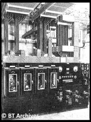
Guardian performed the function of a Zone Trunk exchange for the Manchester region, employing Strowger motor-uniselectors. The colocated repeater station used thermionic valve equipment, the high tension (HT) power supplies can be seen in the gallery.
Guardian Exchange Gallery
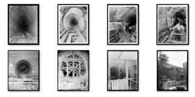
Guardian like Birmingham Anchor used concrete lined tunnels, whereas London Kingsway used segmented cast iron or concrete sections bolted together. Kingsway was originally built by London Transport using the same technique as they employed for rail tube lines.
Guardian Construction Gallery$$
Rutherford Exchange building containing the lift in shaft 5 and the Central Exchange opposite, bounded by Chain St & Pine St, which was the main pedestrian access are now office buildings. Shaft 5 has been capped off and access blocked from both buildings. Shaft 6 remains as the only access point to Guardian. The cable tunnels running up Nicholas St, not shown in the plan have their own access points elsewhere across the city.
Guardian was the last deep underground exchange to be built before the change in policy described in the first topic on this page in CAB134/2135. Other zone exchanges were built with secure accomodation, for instance, Leicester Wharf St. was in the basement and had large blast doors that could be shut if necessary. In recent years the building has been converted to flats. Coventry Leofric basement apparatus room has a blast door in front of the normal wooden doors.
Coventry Leofric Blast Doors
Hardened Repeater Stations
The connection between the home telephone and the exchange is carried on a single pair of wires. Over the relatively short distances involved, it is economical to bundle these together in large cables, some containing as many as 2000 wires. Over long distances, the use of large cables is not economic. A system of multiplexing 24 analogue speech channels into two pairs of wires was developed. Further developments increased this capacity. By the 1960s a 4MHz co-axial cable could carry 960 channels on two coax tubes, one for each direction of speech. Today 40GB optical fibres have 10,000 times this capacity.
When telephone calls are sent down a long pair of wires between exchanges, the audio signal must be amplified at regular intervals. The amplifying point is called a Telephone Repeater Station (TRS). Most large telephone exchange buildings incorporated a TRS area too. In small exchanges, a special area wasn't warranted for the TRS, in this case the amplifier racks were placed alongside the switching apparatus.
On long distance routes using multiplex equipment, the bulky thermionic valve equipment was housed in a dedicated TRS building, rather than using part of the exchange building. Early coax cables carrying television or multiplexed speech channels required amplifying every couple of miles. Hundreds of TRS were housed in small brick buildings the size of a garden shed. As the amplifiers became transistorised it was possible to house them in special cases in manholes, saving the expense and difficulty of procuring land for a TRS.
Above ground repeater stations were vulnerable to damage in a war, when it was thought that only a few locations might be targets for atomic bombs, a decision was made to protect the important routes with specially hardened buildings. At the same time the three underground exchanges were being built, a small number of hardened repeater stations were constructed to house repeater equipment. Only eight of these repeater stations were actually built, six PR1 type and two larger PR2 type before the policy changed. After the development of the more powerful hydrogen bomb and a greater number of possible targets, both military and centres of population, the policy changed to 'Safe As Possible' and the duplication of important circuits each routed separately.
Construction of a Protected Repeater Station
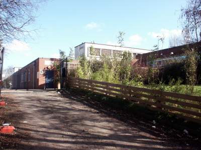
A two storey semi-sunken hardened repeater station was constructed in 1954 in Sheldon, a suburb on the East side of Birmingham. Known as Lyndon Green (BM/D), it was contemporary with the secret underground exchange, Anchor in Birmingham City centre. In the gallery there are pictures of the property taken in March 2009. The hardened concrete core has brick built offices attached. A similar hardened repeater station was built at Queslett, a Northern suburb of Birmingham, and now houses the 'Beacon (CMBEAC)' telephone exchange.
Lyndon Green Hardened Repeater Station$$
List of GPO Protected Repeater Buildings
Birmingham, Lyndon Green (BM/D) on the Coventry Road, Sheldon Lat/Lon 52.456473,-1.794832 OS. Map SP141842 is just visible behind the trees on Street View [Aug 2017] Still present 2024.
Birmingham, Queslett (BM/H) Whitecrest Road, Queslett B43 6EE, Lat/Lon 52.547349,-1.924963 OS. Map SP051943 clearly visible on Street View [May 2016] now used as Beacon telephone exchange. Still present 2024.
Glasgow, Uddingston (GW/J) located in Holmbrae Rd, Uddingston, Glasgow G71 6AN, Lat/Lon 55.827916,-4.081661 can be seen on Google Street View [October 2016]. By 2001 was repurposed as Clyde Valley exchange containing Glasgow Moissanite NGS and Carrick DMSU. Still present 2024.
Leeds, Rothwell Haigh (LS/D) repeater station at Sharpe Lane, Wakefield, WF3 3AW, Lat/Lon 53.743787, -1.508981 served a now disused RAF communications centre immediately behind it, both have been demolished and used for housing. The remains of the rubble from the PR2 building can be seen on Google Street View [June 2008]. The nearby blockhouse is the Gas supply emergency control centre.
Manchester, Stockport (MR/G) the hardened repeater station is colocated with the exchange at Brundret St, Stockport SK1 4LW, Lat/Lon 53.403056, -2.148327 and visible on Street View [October 2014]. Still present 2024.
Manchester, Swinton RS (MR/F) building in Lawnswood Drive, Swinton M27 5NH, Lat/Lon 53.503875, -2.325614 has been demolished and used for housing, becoming the northerly side extension to Lawnswood Drive.
Portsmouth, Portsdown (PT/C) repeater station in New Down Lane, Cosham, Lat/Lon 50.855192, -1.058817 OS. Map SU664066; is clearly visible on Street View [May 2011] Still present 2022 but no longer a BT building.
Warmley (XEX) near Bristol once handled circuits from the Central Government War Headquarters 'CGWHQ' bunker in Corsham, but this PR2 building has long since been demolished and is now Springley Court BS15 9RA. Lat/Lon 51.459935, -2.487027 The OS Map Ref given on Sub-Brit is wrong, it should be ST 6626 7355.
The bracketed letters in the list above are the THQ1141 Engineering Code for the repeater station. The Latitude and Longitude numerical values may be copied and pasted into Google Maps or Bing Maps search box.
GPO records in BT Archives show these were the only specially constructed hardened buildings. International undersea cable landing points at Oban and St Margaret's Bay included protective tunnels. Other GPO / BT buildings may have been strengthened too. Hardened buildings were built for military communications (BOXER / UNITER), but they are beyond the scope of this website.
The Images from BT Archives are Copyright BT Heritage, licensed under a Creative Commons License


 The Images from BT Archives are Copyright BT Heritage, licensed under a