From the Archives
This topic is based on information held by the National Archives at Kew, Civil Defence Planning in the late sixties, kindly supplied by Dave of 'radiohistory.uk'. Hitherto the LDN had been the source of much speculation.
The minutes of a meeting on 18th April 1966, for the purchase of H/F transportable Wireless Sets to be used by Civil Defence sets the scene. Note: In the sixties, RSG's and Sub-Regional controls were the names given to Regional Government Headquarters (RGHQs) this final name is used throughout this website.
The meeting was called to consider the specification of the transportable H/F wireless sets recommended by the 1965 Working party on Communications for the Control System, and prepare a purchasing programme for the 1966/67 financial year.
The essential function of the equipment is to give skeleton and flexible communications in the immediate pre and post attack phases between R.S.G. Groups, Sub-regional Controls and selected local authorities. To do this it must work independent of relay stations, be transportable from base to base, be capable of use independent of mains power and give links between groups and Sub-Regions located at distances apart varying from 10 to 125 miles. An important point is that the Group centres will not be capable of receiving equipment in peacetime. It must, therefore, be easy to install and operate without special skills.
The essential function of the equipment is to give skeleton and flexible communications in the immediate pre and post attack phases between R.S.G. Groups, Sub-regional Controls and selected local authorities. To do this it must work independent of relay stations, be transportable from base to base, be capable of use independent of mains power and give links between groups and Sub-Regions located at distances apart varying from 10 to 125 miles. An important point is that the Group centres will not be capable of receiving equipment in peacetime. It must, therefore, be easy to install and operate without special skills.
Mr. Morley informed the meeting . . . . Typical 100 watt portable equipment was in commercial use for communications over considerable ranges in peacetime (when ionosphere conditions were normal) but in the attack phase when only ground wave propagation might be possible we could rely on no more than 20 to 30 miles effective range . . .
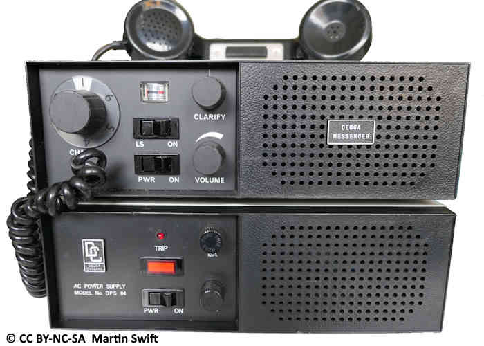
Home Office Communications Branch, produced Outline Specification No. 58 (April 1966) for the tendering process. Five manufacturers offered their products. G.E.C. RC420TR; Marconi H4000; Pye SSB125T; Racal TRA355; Redifon GR410
These tenders were considered at a meeting on 5th August 1966, where is was decided to purchase the Pye SSB125T although they were unable to decide whether to purchase the battery or mains version. The minutes of this meeting refer to the network as 'Last Ditch'

. . . The equipment is quite commonly produced to give switch tuning between 4 working frequencies and it has been accepted that this would be adequate to meet the prime need for a cheap, simple, reliable, and readily obtainable "last ditch" means of communication.
An addendum dated 12th August 1966 was added to the minutes by R. L. Jones. This gives an insight into the availability of standby mains power at that time.
3. As regards powering of the sets, I am now reasonably satisfied that we need at least 100 battery operated sets whatever the relative cost may be, because we could not count during the next calendar year on having more than 13 S.R.C.s, or than about 30 of the selected local authority controls equipped with emergency standby power, and the number with standby power will grow fairly slowly. . . .
At a subsequent meeting on 15th August, it was decided to purchase 100 battery sets and 50 mains operated ones to be used where standby power already existed. The minutes of this meeting also give an insight into the frequencies used by the LDN. Note: m/cycles or Megacycles has been superseded by Megahertz ( MHz )
It is expected that 30 frequencies will be obtained, 10 between 2.5 and 3.5 m/cycles and 20 between 3.0 and 5 m/cycles, 10 of the frequencies between 3.0 and 5 m/cycles would be useable for peacetime training, the others would become available after declaration of a war emergency. A final decision will be given during the course of the week.
Mr. Morley said that the frequencies could be used at least twice up and down the country so giving not less than six frequencies per Region (compared with the 4 frequencies previously stated to be the acceptable minimum).
In discussion about the desirability of keeping in touch with the Army. H/F transmissions, Mr. Morley pointed out that the Army D.11 sets would work over long distances and would use different frequencies at different times of day according to the conditions. In civil defence however, it would not be possible to allow more than one channel for the Army contact. A solution, later, might be to listen in by means of Army equipment.
 This page is Copyright © RINGBELL.CO.UK, under a