This page gives an overview of the development of the UK's early warning system while avoiding too much technical details. Should you wish to read an in depth description of the two incarnations of the warning system, please use the website menu and select the WB400 & WB600 for the system between the sixties and eighties, or WB1400 Parts 1 & 2 for the eighties to its closure in 1992.
Standardised Warning Messages
The nuclear warning system in the U.K. was based around colour coded messages and their associated warning signals. It was an extension of the system used in World War 2 to inform the public of two messages 'Attack Warning' and 'Raiders Passed' by using sirens. The siren control buttons were coloured red and white. In the nuclear bomb era, these siren signals became 'Attack Warning Red' and Attack Message White', the warning of Nuclear Fallout was added in the form of a Grey and Black warning.
The Beginnings in WWII
World War 2 established the principle of placing air raid sirens under the control of the police. This continued in various forms until the end of the cold war period in 1992 when the Air Raid warning network was discontinued.
During WWII centralised control of Air Raid sirens by the police was introduced, but there was no National Warning system, instead the local police received notification of enemy bombers in the vicinity and when they had passed. A clue to how the warnings were propagated in WWII are given in the GPO report of the development of the the new nuclear warning system. The system allows audible warning and verbal information to be passed, simultaneously, to a large number of recipients within an air raid warning district, without the need for Post Office operators to make individual calls to police, fire stations, air raid wardens etc., as was necessary in the last war.
It has always been possible to set off the power siren by means of an on-site local control unit, the Autowailer, situated close the the siren fuse panel. Examples of Autowailers and fuse boards can be found on this website. To avoid the need to staff each siren point, remote control from Police Stations using dedicated private wires fitted with control apparatus designed and maintained by the British General Post Office (GPO) were introduced.
Nuclear Weapon Era
The 'ATTACK WARNING RED' message is signalled by a rising and falling sound of a hand-operated or electric mains driven siren. The approximate timing being 4 seconds rising and 4 seconds falling sound.
The 'GREY WARNING' was intended to give a one hour notice of impending fallout, by using a siren fitted with flaps to interrupt a steady siren sound. As alternative the ringing of church bells, or in Scotland where church bells are not in common use, by whistle. The proposed use of a Grey Warning was abandoned by the early nineteen sixties.
The 'FALLOUT WARNING BLACK' announced the arrival of fallout in a particular area known as a warning district. The signal primarily was firework maroons sending three shells high into the sky before exploding - Bang - Bang - Bang or by three gong sounds or three blasts of a policeman's whistle.
The 'ATTACK MESSAGE WHITE' is 60 seconds sounding of the siren with a steady note indicated you could leave your shelter as the raid had been thwarted or if there had been nuclear explosions, the fallout radiation had dropped to a safe level.
Due to the now supersonic speed of aircraft and the use of missiles it was vitally important that any attack message should be propagated quickly through a national warning system. The development of this warning system is summarised in topics further down this page.
The Threat of Nuclear Attack
After WWII it was considered the enemy might attack using aeroplanes that would be detected by radar but soon the use of Inter Continental Ballistic Missiles ( ICBM ) became a major concern. The U.K. did not develop its own ICBM radar but instead negotiated with the American's to host part of their system at Fylingdales and receive warning of a missile attack from them.
Attack from Aircraft
During the Cold War, radar techniques developed at a pace. The original WWII radar stations were superseded by the ROTOR radar sites in 1952-53. By 1955 ROTOR had been abandoned for a system of Master Radar Stations. Later these were replaced by the Linesman / Mediator system. This in turn was replaced by improved equipment. It is beyond the scope of this web site to explore the development of the UK land based radar systems. It is sufficient to say whatever system was in place it would detect approaching hostile aircraft resulting in the scrambling of UK fighters to investigate. Had these hostile aircraft not turned away from the UK an Attack Warning would have been issued.
Attack by Intercontinental Ballistic Missile
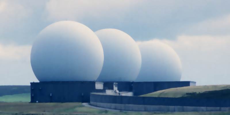
Fylingdales RADAR Station
This is the familiar sight of Fylingdales, Ballistic Missile Early Warning System (BMEWS) station during the Cold War period. Constructed during the early sixties as part of a chain of radars protecting the USA. The famous golf ball radomes were replaced in 1992 with an upgraded system consisting of a pyramid construction housing a phased array radar.
Detection Pattern
Each of the three radomes contained a rotating radar head with a range of about 3000 miles. One head scanning at an angle of 2.5° above the horizon and another head scanning at 5° above the horizon. A missile launch would cut through both of these beams in turn. The third radar capable of tracking many separate objects simultaneously would track the missile and calculate its trajectory.
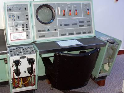
Situation Display Console$
If the calculated trajectory and other characteristics were thought to indicate it to be a missile the Situation Display Console would have warned of the impending attack. The BMEWS system at Fylingdales was one of three operated by the United States as part of their early warning system. The three stations were connected back to the USA via a series of tropospheric scatter radio links.
Many parts from the Cold War era Flyingdales radar station were, until recently, exhibited at the Radar Museum at RAF Neatishead, Norfolk. The photograph of the Situation display console was taken there in 2005.
The left hand table leg of the situation display contained a phone console. The bottom right button is marked 'MOD' and connected the console operator to the Ministry of Defence (M.O.D.), Strike Command at RAF High Wycombe. The top right button marked 'UKWMO' connected with the United Kingdom Warning and Monitoring Organisation (U.K.W.M.O.) at Preston. If the expected target was in the U.K. the console operator would have used these phone links to communicate the bad news
Four Minute Warning
Either BMEWS at Fylingdales or one of the RAF radar stations would have contacted Strike Command at High Wycombe or the 'standby' UKWMO centre at Preston. At either location a senior member of the UKWMO would issue the public Attack Warning RED via the HANDEL system, which is described in detail on this web site. Unless the attack was launched from a submarine close to our shore it was expected to be able to issue the public with a 4 minute warning of an impending attack. Some commentators have suggested that a 3 minute warning was more realistic.
Detection Failure
If the first nuclear device had managed to slip through undetected by BMEWS or Radar its detonation would have been spotted by the Royal Observer Corps (ROC) whose monitoring posts formed part of the UKWMO. The information about the unexpected strike would have been fed back via the UKWMO communications network to its Preston Sector Headquarters and the Air Defence Operations Centre at RAF High Wycombe, so either could issue the Attack Warning for the rest of the country.
Development of the Public Nuclear Warning System in the UK
The United Kingdom Warning and Monitoring Organisation (U.K.W.M.O.) was set up in 1957 to give the military and public a warning of possible air attack and fallout from nuclear weapons. At the time there was no national system to convey these warnings. Even before the establishment of UKWMO under Home Office control, work was underway in the G.P.O. to develop an early warning system. Progress was slow due to the lack of government funding. The G.P.O. Engineer-in-Chief's annual reports give an insight into the progress.
The G.P.O. E-I-C report for 1950 / 51 Tells of early development work. At the request of another Ministry, a single-channel carrier wire broadcasting system has been developed which could be used to provide a special "broadcast" information service. Equipment has been installed for a pilot experiment and has been used to demonstrate its potentiality as a means of providing simultaneous one-way communication from a few control centres to many receiving points. and goes on to say: Contracts have been placed for further single-channel equipment which will enable a full-scale field trial of the system to be made over an area of 400 square miles to subscribers on nearly 50 telephone exchanges. This is some 10 years before the full rollout of the warning system.
Extracts from the 1951 / 52 report say: Intensive development work on the carrier wire broadcast system for use in distributing special information, e.g. civil defence warnings continued (see last report page 44). Under Home Office authority, work was put in hand, in April 1951, to provide experimental apparatus and equipment for a field trial at Bristol. The system allows audible warning and verbal information to be passed, simultaneously, to a large number of recipients within an air raid warning district. . .
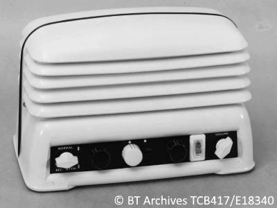
Equipment has been installed in the outer area and 350 subscribers have been connected to the system for the purpose of the trials. The apparatus required at the subscriber's installation consists of a carrier receiver, filter unit and standby 6-volt car battery provided to cater for mains failures at subscriber's premises, under emergency conditions. The carrier receiver is illustrated . . [Receiver Carrier WB200A]
Receiver Carrier WB200A$
This early development work used mains operated thermionic valve receivers, using similar circuits to those in household radio receivers from the nineteen fifties. The Carrier Receiver WB200, looks very much like a radio of that period. The black bottom panel houses three white and two black knobs, plus an On and Off switch.
In the image gallery, we have photographs from the BT Archives of the Receiver and a typical installation with incoming line and filters and battery. Operating Unit WB 200A, this was the Carrier Control Point equipment for use in the police station. Adapted from the case of the House Exchange System No. 1 & No. 2, officially known as the 'Telephone, Intercom., No. 1/1 or 1/2', its much less bulky and more elegant than the WB400 production unit. The final image in the gallery is the Control Unit WB 203A, presumably containing all the carrier generation equipment at the control point.
The E-I-C 1952 / 53 Report, details the results of the "Carrier Wire Broadcasting System for Civil Defence" trial. The field trial of equipment designed for distributing civil defence messages over working audio junctions and local lines was completed at the end of August 1953, after a successful run of 14 weeks. During this period, operation of the trial was under control of the Home Office who arranged for test messages to be sent out twice daily. On completion of the operational trial, the subscribers' receivers were recovered but the exchange equipments at 29 exchanges were kept in operation and have been tested at three-monthly intervals; a number of receivers were also put on life test.
The field trial showed a number of ways in which the design of the equipment could be improved and further development work has been undertaken. The design of the equipment has been modified to provide for the simplification of the facilities offered, improved performance (particularly with regard to quality of received speech) and the use of dry batteries instead of secondary batteries to operate subscribers' receiving equipment in the event of failure of the mains power supply. Further attention has also been given to the design of testing equipment.
Progress seemed very slow with many delays, the 1956 / 57 Report indicates the position five years later. Financial authority for installation of the system . . . was expected but did not mature during the year under review. Drawings, specifications and final prototypes were prepared and held in readiness.
The delay enabled further development work to progress, so by 1958: Financial authority for the scheme referred to in the 1956-57 report (page 69) was not received during the year. Work was commenced on a revised design employing transistors instead of valves, one of the principal aims being to increase greatly the duration of working in the event of mains failure.
With the cold war beginning to hot up, the E-I-C 1959 Report said: Work on the redesign of the equipment to employ transistors instead of valves (1957-58 report, page 67) proceeded slowly in the first half of the year under review, but it was speeded up on indication that authority for implementing the scheme might be forthcoming. Instructions to proceed with the scheme were received in January 1959
The system designed so far was for a speech broadcast system from Police Control Centres to Warning Recipients. The next report indicates that a siren control system would be added later.
The E-I-C 1959 / 60 Report, shows that progress was now being made. Redesign of the circuits to employ transistors was completed in the year under review. The system was coded Carrier System WB 400. Authority was received for Stage 1 - comprising 2,700 exchanges, 150 control centres and 14,000 subscribers' receivers - to be completely installed by March 1962. Orders were placed for some small items of the equipment, and negotiations were commenced with three transmission equipment contractors on the design for production of the control and exchange equipments. Extensive field tests were made of the interference from radio stations that may be experienced on the system. A radio interference balancing unit was designed for use on lines containing open wire. Planning of the junction network for Stage 1 was substantially completed by the Regions and Directorates concerned. Work was commenced on a v.f. signalling system for the remote control of public warning devices as an additional feature on the Carrier System WB 400.
The first mention of using the Speaking Clock network to propagate warning messages to every police control centre was first mentioned in the 1961 / 62 Report in a very guarded way. V.F. and speech equipment for a national network to feed warning information to the carrier control centres was designed and ordered.
By the 1963 Report, some parts had been installed: By the end of the year orders had been placed for equipment at 254 control centres, 5,500 exchanges and 21,500 receiving points; 79 systems had been installed of which 24 had been handed over for service. Development work was continued on a system for remote control of public sirens by means of v.f. signals over the Civil Defence carrier system. Development work also continued on sub-audio signalling equipment intended for the distribution of local call timing meter supply pulses to U.A.X.s over the Civil Defence carrier system. GPO BT staff will know this later system as WB700, which is described in a page found in the website menu Alphabetic Index along with other wire broadcast systems, such as the WB300 for the Atomic Energy Authority which leapfrogged ahead of the WB400 in its implementation.
Work on the speech broadcast system was substantially complete by 1965. By the end of the year the 250 carrier systems (WB 400), together with the associated equipments terminating the national audio network connected to the central source of information, had been completed and approximately 20,000 receivers, distributed over 5,500 exchange areas, had been connected. Additional receivers are being connected, as required by the Home Office. The design of the v.f. signalling system (WB 600), for remote control over the WB 400 networks of all power operated sirens, was completed and contracts were placed for control equipments and for 7,400 siren point receivers. Work on the siren control system was mentioned in the 1967 E-i-C Report: Carrier System for Civil Defence. The extensions to the WB 400 system were connected and the installation of the siren control system (WB 600) was substantially completed.
Overview of HANDEL
This topic is nicely summed up by BT Telecom Instruction B3 C0272 (March 1982). It first two paragraphs of this Sales Procedure document are relevant here.
1 UNITED KINGDOM WARNING AND MONITORING ORGANISATION (UKWMO) This organisation is responsible for warning the public of an imminent air attack or the approach of nuclear fall-out. The issue of an attack warning will bring into action the Handel and Carrier systems which have been designed to enable a warning to be issued rapidly. Fall-out warnings will be issued from information provided by the UKWMO Royal Observer Corps (ROC).
2 HANDEL Handel is the name given by the UKWMO, and for convenience also used by British Telecom, to the special unidirectional network and associated apparatus which has been provided to connect the Air Defence Operations Centre, from which an attack warning would normally be issued, to the Carrier Control Points (CCPs).
The codeword HANDEL, derives its name from Georg Friedrich Händel, whose Oratorio 'Judas Maccabaeus' contains the movement (Pt.2, No.45) whose title 'SOUND AN ALARM' is the motto of the UKWMO, as well as describing the function of the system.
1st and 2nd Generations of HANDEL
Outline of HANDEL used between 1962 - 1992
In the fifties and sixties, the General Post Office (G.P.O.) was a government department with a monopoly of landline communications and licensed wireless communications to other bodies including the BBC and Police. After many changes over the years, Post Office telecommunications branch became British Telecom ( BT ) a private company without the monopoly it once held.
The G.P.O. introduced the Speaking Clock service in London in 1936. It was an instant success and the service rapidly spread to all exchanges throughout the U.K. To avoid interruption to this important service, the Speaking Clock or Time Signal (TIM) as it was also known was distributed on a duplicated rings of lines between major telephone exchanges designed to raise a fault alarm if a ring failed. The distribution amplifiers at these major exchanges would switch to the other ring circuit should the one currently in use fail, thus maintaining the time service.
A national communications system was required to convey the attack warning from either of two command centres to 250 control points in police stations all around the United Kingdom. The Speaking Clock distribution provided a ready made and secure (against breakdown) system of distributing the national warning messages. Branches off the two Speaking Clock rings were taken on two diversely routed pairs of wires to the Police Station's control point.
The Attack Warning would be derived from military radar and the USA's Ballistic Missile Early Warning System. But fallout warnings and the eventual all clear was the responsibility of the U.K.W.M.O. To facilitate this, each of the 25 UKWMO Group Controls were connected by landline to all the police station control points within their coverage area.
Police station control points broadcast voice messages for the attack warning, fallout warning, all-clear and special tones for controlling sirens, by using a radio frequency carrier signal sent over normal telephone circuits. For this reason the police station broadcast control point was known as the Carrier Control Point ( C.C.P. ). The carrier had no effect on the operation of the telephone line and the avoidance of Private Wires (also known as Private Circuits) used in the previous WWII system, reduced the implementation cost and improved reliability.
The 1st. generation of HANDEL and carrier networks were installed during the early sixties. During the eighties they were upgraded to a 2nd generation HANDEL and carrier network, which served until 1992, the end of the cold war period.
On 10 July 1991, Home Secretary, Kenneth Baker announced in parliament, that after a review of emergency planning, he had decided to stand down the R.O.C. Then following the Chancellor's autumn statement in parliament on 12th November 1992, the Home Office announced with immediate effect the UKWMO would no longer function. HANDEL and the carrier broadcast system were decommissioned shortly after. Throughout its life the equipment was installed and maintained by what started as the GPO, then became Post Office Telephones and finally British Telecom.
In 1984 the earlier mechanical speaking clocks were replaced by electronic units using memory devices to store the time message sections. The electronic clocks and analogue distribution network continued to serve the U.K. after the closure of HANDEL in 1992. All remnants of the HANDEL distribution network were removed in 1994 when the analogue speaking clock rings were replaced by digital Recorded Information Distribution Equipment ( RIDE ). These racks of equipment, located in Digital Main Switching Units, were fed with digital announcements and the Speaking Clock supplied by 2 M/bit rings emanating from the B.T. Network Operations Centre near Oswestry.
Initiating a National Attack Warning Red
The National Air Attack Warning message would originate not from military personnel but from a Home Office Principal Warning Officer ( PWO ) stationed at a location known variously as Strike Command (SC), Air Defence Operations Centre (ADOC) and then Primary War HQ (PWHQ) at RAF High Wycombe. If the High Wycombe HANDEL centre were to be destroyed or disabled, the national message could be sent from the other HANDEL centre at the UKWMO Western Sector Control (Preston) at Goosnargh near Preston, Lancashire. Preston received a feed from Enhanced Recognized Air Picture Dissemination System (ERAPDS or e-Rapids) so it could see the same countrywide radar view available at High Wycombe and other RAF locations.
The U.S. Ballistic Missile Early Warning System radar site at RAF Fylingdales, Yorkshire had private circuits to both RAF High Wycombe and UKWMO Preston.
If nuclear detonations were detected by Royal Observer Corp (ROC) monitoring posts without a national attack warning being given, the UKWMO had processes in place to inform the SC/PWHQ/ADOC to enable them to retrospectively give a national warning. As a backup, in case both National Centres be disabled, or the HANDEL network itself, the 25 UKWMO Groups HQs were also instructed to call each CCP within their area requesting they broadcast the Attack Warning Red.
Initiating a Fallout Warning or All Clear
During and following the attack, the network of ROC monitoring posts would report details of bomb detonations and local radiation levels to their UKWMO Group headquarters. The network of Group and Sector headquarters would exchange data to create a national picture of detonations and both the actual and predicted fallout patterns. As fallout does not respect national boundaries the UKWMO had liaison officers at Sector headquarters exchanging data with similar organisations in other European countries. Even if the UK was not directly attacked, we would need to know that we may receive fallout from bombs in neighbouring countries.
The 250 carrier broadcast control points give too granular coverage of the country for effective fallout warnings. So the country was further subdivided into smaller areas of approximately 100 square miles, known as warning districts. The UKWMO would predict the possible fallout levels in each warning district. Then using their direct line to the CCP, request the police issue warnings for the affected districts.
Following a National Attack Warning, if the attack failed to materialise, was intercepted or the raiders didn't use nuclear weapons, an All Clear message White may be issued at National level from SC/PWHQ/ADOC control centre.
Should the attack succeed, when the fallout radiation levels had returned to a safe level, probably after a period of two weeks, the All Clear would be notified to the police station CCP by UKWMO Group control.
Overview of Carrier Broadcast Systems : 1st and 2nd Generation
Police Station Control Point
The UK was divided into 250 Carrier Control Points (CCP) located in a major police station. The CCP has duplicate HANDEL handsets to receive the national messages. During peacetime the speaking clock can be heard on these handsets. A third handset connects to the UKWMO ROC Group Headquarters serving the area in which the police station is located. This would be used to receive any Fallout Warning messages and eventually the All Clear.
This is a two stage system, onward distribution of public warnings required human intervention at the police station to retransmit the message. Neither Strike Command nor the ROC had any direct way of alerting the end user at the warning point. This is a continuation of the method of warning the public introduced during World War 2.
Copper pairs between a telephone exchange and customers premises are able to carry signals well above the range of human speech. This extra bandwidth may be used to carry signals without interfering with the normal telephone operation. Broadband Internet using ADSL is a modern system utilising this extra bandwidth. However other simpler systems known as "Wire Broadcast" (WB) have been around since the forties. A paper read to The Institute of Post Office Electrical Engineers on the 11th April 1949, describes the trial of a multi-channel carrier system for broadcasting BBC radio programs over telephone lines. It had been hoped this would improve the audio quality compared with Medium Wave wireless broadcasts.
At the Police Station, the Carrier Control Point (CCP) equipment, uses Wire Broadcast, a 72 kHz radio frequency carrier modulated with speech or tone signals for civil defence purposes. The carrier is distributed via the main telephone exchange, known as the Control Point Exchange (CPE), to all the warning points. To provide security against a fault going unnoticed, carrier was distributed throughout the network using existing telephone lines. This helps detect faults in the carrier system and saves the cost of providing extra wires often to remote locations. If the wires become disconnected the telephone would be reported faulty, long before the carrier system was next tested. Filters separated the telephone and carrier signal allowing both to be used simultaneously.
It has been wrongly reported in the past that the 72kHz carrier was broadcast over the Speaking Clock system. Such as - RSGB RadCom July 2001, 'The Voices' Page 35. This myth may be found in the chatter on the uk.rec.subterranea news group too. This is clearly not true as the speaking clock only distributed audio voice messages.
Countrywide there were 11000 fallout warning points, each with a carrier receiver, spread out amongst roughly 750 fallout warning districts. A small number of warning districts are grouped into a Carrier Control Area (CCA) each with its own police Carrier Control Point (CCP) of which there are 252 countrywide. Each of 25 ROC Group HQ issue fallout warnings to the warning districts within their boundary, via the CCP serving that district.
Each CCP is allocated a unique three digit number, those numbers are listed in a separate chapter on this website please follow the link at the bottom of this page. Warning points within that CCA are numbered sequentially starting at one and prefixed with the CCA number and a stroke to identify them individually across the country. For example: Bristol ROC Post at Upper Sapey is Warning Point 052/38 (No.38 on Worcester CCP), Bristol ROC Post at Penhow is 043/38 (No.38 on Newport CCP).
The network of GPO / BT circuits comprising the carrier control area were allocated 'Private Wire' (PW) numbers in the series 103xxx where 'xxx' is the Carrier Control Area (CCA) number. For example, Swindon PW/SW 103031,Londonderry PW/NI 103290. The PW number is used for fault reporting and records purposes. In modern terminology a private wire is now known as a 'leased line' or 'private circuit'.
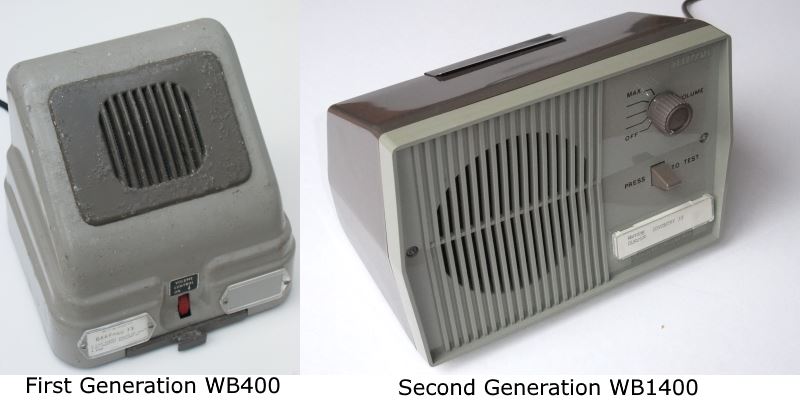
Public Warning Receiver
The warning receiver is the part of the system most visible to the general public. The normal telephone line at the premises carried the carrier signal from the telephone exchange to the receiver.
Both Generations of Warning Receiver
In rural areas there were no power operated sirens, so speech receivers were located in premises such as Post Offices, Shops, Pubs, Vicarages or the homes of Police Officers, Council Officials or magistrates, who were deemed "responsible" people trusted to warn the local population by the use of hand sirens, whistles, maroons and gongs. Around 18,000 Warning Points existed nationally.
Warning Points in Dorset
Additionally a warning receiver was likely to be found on the premises of about 4,000 Warning Recipients who would need to know if it were safe to go outside. These would be Fire Stations, Police Stations, Hospitals, Public Utilities and Feeding stations to name a few.
In the earlier carrier receivers the instructions for the Warning Points were given on a card held in a drawer in the base of the unit. In the later receivers, the instruction card is retained under a clip on the speaker, some police forces issued users with a detailed instruction booklet. Both sets of instructions are reproduced on their relevant pages.
The Images from BT Archives are Copyright BT Heritage, licensed under a Creative Commons License.
 The Images from BT Archives are Copyright BT Heritage, licensed under a