This topic describes the second incarnation of the HANDEL Nuclear Attack Warning system, known as Wire Broadcast System WB1800 and the carrier equipment designated Wire Broadcast System WB1400. WB1400 replaced both the Verbal Warning WB400 and Siren Control WB600, in areas with a flood warning system, it also replaced the WB601.
Home Office archive file HO393/63 tells us the expenditure on new carrier circuitry (known as WB1400) from and including the CCPs is costing a total of £24.6 million between 1982/83 and 1987/88.
This is the first of a two part topic. This part, describes the broadcast of national attack messages to the carrier control points, the control point exchange and routine testing. Part two, covers the distribution through the BT network to the customers local exchange then distribution from the final exchange to customers speech and siren receivers.
Full Technical Description of HANDEL
Neil Harding the designer of the WB1800 HANDEL Network has kindly provided this description of the system he created in the nineteen eighties to replace the sixties network used in the WB400 era. I took the operating unit photograph at Hack Green Museum, and kindly thank Graham Carlisle for the gallery photographs of the table mounted control console and rack mounted test panel, in this section.
1. Introduction
The HANDEL system was designed to provide direct communication from two injection sites to 250 carrier control points (CCP) located in major Police stations and other locations. The CCPs would then forward warning messages over the WB1400 broadcast networks to receiver points. It’s function was to initiate a national early warning of nuclear attack by missile or manned aircraft on the UK. The carrier control points would also initiate operation of the siren sequences (Attack Warning, All Clear). The WB1400 carrier control points could also initiate flood warning siren sequences however this would be initiated by a message from the Local Authority. In the case of missile attack the early warning would be occur approximately 4 minutes prior to impact and in the case of manned aircraft attack the warning would be occur approximately 15 minutes prior to impact.
2. The System.
There were two HANDEL operating points known as Injection Sites. The primary injection site was at HQ Strike Command at RAF High Wycombe. The operating unit was located in the ADOC cell in the RAOC bunker. The Home Office UKWMO staff shared a ‘cell’ with the air defence operation staff and had sight of the BMEWS and EUCOM displays. The other location was in the Central operations area of the UKWMO wartime HQ/ROC 21 Group HQ Bunker in Langley Lane, Goosnargh near Preston. This location was also equipped with a BMEWS terminal.
3. The Network
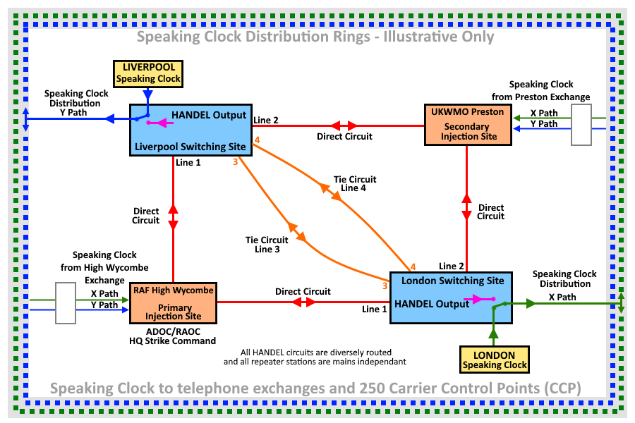
Refer to the network schematic. The HANDEL system used the PO/BT speaking clock network for distribution to the carrier control points. The speaking clock network was a duplicated network with two speaking clocks and associated distribution amplifiers, one located in London and the other in Liverpool. The speaking clock network ran as two rings around the country in opposite directions connecting to group switching centres and exchanges for time distribution to customers and to control point exchanges (CPE) for the HANDEL function . The Injection Sites were directly connected to each speaking clock switching site and the switching sites were interconnected by 2 tie circuits to overcome the problem of failure of a directly connected circuit.
Circuits in the HANDEL Network
4. Network Condition - Unoperated
Before the system is operated the conditions on the Injection Site operating unit (Unit WB1800/1A) will be no lamps lit and the X and Y meters responding to the speaking clock signals. Test links at the injection sites and switching sites will be in the normal position. The speaking clock will be heard in the X and Y handsets at the CCPs
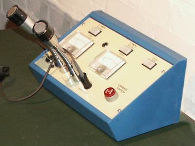
WB1800 Operating Unit, displayed at Hack Green Museum
5. Network conditions – Operated
5.1 Operating the system at a HANDEL Injection Site
5.1.1
Action.
Plug in the headphones.
5.1.2
Response.
Check that the speaking clock can be heard in both earpieces X (London) on the left and Y (Liverpool) on the right.
5.1.3
Action.
Insert the key into the operating unit and turn ¼ turn clockwise.
5.1.4
Response.
Both the X and Y released green lamps will light.
5.1.5
Action.
Press and hold the operate switch.
5.1.6
Response.
The 2kHz monitor tones on the direct Private Circuits to the switching sites will turn off followed by simultaneous transmission of P+Q seize tones 1200Hz and 1440Hz (These are the new tones for the new HANDEL system and WB1400). The P+Q tones will last for 4 seconds.
5.2 Response and functions of switching equipments in Normal Mode
Normal Mode is when both direct Private Circuits are intact.
5.2.1
After 1 second of P+Q tones both switching equipments will be 'seized' via the direct Private Circuits and the following responses will occur.
The 2 speaking clock signals will be switched off and the line seizing the equipment will be connected to the speaking clock distribution network. The remaining burst of P+Q tones (3 seconds) will transmitted over the speaking clock networks to the control point exchanges, to the injection sites over the speaking clock networks and over the return path of the direct Private Circuits to the injection site. The injection sites will be connected to the speaking clock distribution networks and not the return path of the direct Private Circuits so no response will occur as a result of signals on the return paths of the direct Private Circuits at the injection sites.
All HANDEL Private Circuits line fail alarms are suppressed.
3 seconds of P+Q new tones will be heard on the X and Y earpieces on the HANDEL operating unit headphones at the injection points. The X and Y meters will respond to the P+Q signals.
After the tones have been present on the speaking clock distribution networks for 1 second the line receivers at the injection sites will respond and the operating unit green released lamps will extinguish and the red seized lamps will light.
The P+Q receivers at the 250 Control Point Exchanges will respond and forward a 180Hz tone burst to their carrier control point which in turn will give an audible and visual alarm above each of the X & Y handsets.
5.2.2
Once a switching equipment is seized by a line the other 3 lines are inhibited from seizing the equipment.
5.2.3
The switching equipment station alarm will be raised to maintenance staff at both the Switching Sites that a HANDEL switch has occurred.
5.2.4
Tie Private Circuits. When the switching equipments are seized the monitor tones are switched off the tie circuits and the remaining 3 seconds of new P+Q tones are transmitted to the other switching equipment via over the 2 tie circuits. A deliberate priority working has been incorporated so that line 3 will have priority working over line 4. This is achieved by line 3 response time being set to 0.9 Second and line 4 to set to 1 Second. The Line Receive Cards on lines 3 & 4 at both switching sites will give a visual response to having received the seize tones but will not seize the equipment. It has already been seized by line 1, See 5.2.2.
5.2.5
New seize tone regeneration. Because of the possible signal loss between Injection Sites, Switching Sites and CPE (max 12dB, 4dB for direct Private Circuits, 4dB for tie circuits and 4dB for the speaking clock distribution network) it is necessary for resilience to regenerate the P+Q tones. Regeneration occurs at the switching site at the end of the P+Q tone burst from the injection sites and lasts for 1.5 seconds. During the regeneration period speech on the lines seizing the switching equipments are muted.
5.2.6
Old Seize tone generation. Because the change from WB400 to WB1400 will take several years to complete it is necessary to generate the old P+Q tones (2400Hz and 2600Hz) to alert to old WB400 HANDEL equipment. Generation occurs at the switching sites and occurs at the end of the regeneration of the new P+Q tones and lasts for 1.5 seconds. During the generation period speech on the lines seizing the switching equipments are muted.
5.3 Response and Functions of switching equipment when Tandem Working
Tandem working is invoked when a direct Private Circuit has failed, in this case it is assumed that the line from HQ Strike Command to the London switching site has failed.
5.3.1
After 1 second of P+Q tones the Liverpool switching equipment will be seized via the direct Private Circuit and the following responses will occur.
The Liverpool speaking clock signal will be switched off and the line seizing the equipment from RAF HQ Strike Command will be connected to the speaking clock distribution network. The remaining burst of P+Q tones (3 seconds) will transmitted over the Y speaking clock network to the control point exchanges and to the injection sites over the return path of the direct Private Circuit. The injection sites will be connected to the speaking clock distribution networks and not the return path of the direct Private Circuits so no response will occur as a result of signals on the return paths of the direct Private Circuits at the injection sites.
All HANDEL private circuit line fail alarms on the Liverpool switching equipment are suppressed.
3 seconds of P+Q new tones will be heard on the Y earpiece of the HANDEL operating unit. The Y meter will show a continuous signal.
After the tones have been present on the Y speaking clock distribution network for 1 second the line Y receiver at the injection site will respond and the green Y released lamps will extinguish and the red Y seized lamps will light.
The Y path tone receivers at the control point exchange will respond and forward a 180Hz tone burst to the carrier control point which in turn will give an audible and visual alarm above the Y handset.
5.3.2
Once the Liverpool switching equipment is seized by a line all other lines on that equipment are inhibited from seizing the equipment.
5.3.3
The Liverpool switching equipment station alarm will be raised to maintenance staff to notify them that a HANDEL switch has occurred.
5.3.4
When the Liverpool switching equipment is seized the monitor tones are switched off the tie circuits and the remaining 3 seconds of P+Q are transmitted to the London switching equipment via the tie circuits. A deliberate priority working has been incorporated so that line 3 will have priority working over line 4. This is achieved by line 3 response time being set to 0.9 Second and line 4 set to 1.0 Second. The Line Receive Card on line 3 at the London switching site will respond after 0.9 Second and give a visual response to having received the seize tones and will seize the equipment. The Line Receive Card on line 4 will respond after 1 second of P+Q but not seize the equipment because of the line inhibit function described in 5.2.2
5.3.5
New seize tone regeneration. Because of the possible signal loss between injection sites and switching site (max 12dB, 4dB for direct Private Circuits, 4dB for tie circuits and 4dB for the speaking clock distribution network) it is necessary for resilience to regenerate P+Q tones. This occurs at the end of the P+Q tone burst from the Injection Sites and last for 1.5 seconds. During the regeneration period the speech on the line seizing the switching equipment is muted.
5.3.6
Response by London Switching Equipment. After 0.9 Second of P+Q tones on the tie circuits from Liverpool the London switching equipment will be seized via the Line 3 and the following actions will occur.
The London speaking clock signal will be switched off and line 3 seizing the equipment will be connected to the speaking clock distribution network. The remaining burst of P+Q tones (approx. 2 seconds) will transmitted over the X speaking clock network to the control point exchanges.
All HANDEL private circuit line fail alarms on the London switching equipment are suppressed.
2 seconds of P+Q new tones will be heard on the X earpiece of the HANDEL operating unit. The X meter will show a continuous signal.
After the tones have been present on the X speaking clock distribution network for 1 second line X receiver at the injection sites will respond and the green X released lamps will extinguish and the red X seized lamps will light.
The X path tone receivers at the 250 control point exchanges will respond and forward a 180Hz tone burst to their carrier control point which in turn will give an audible and visual alarm above the X handset.
5.3.7
Once the London switching equipment is seized by a line all other lines are inhibited from seizing the equipment.
5.3.8
The London switching equipment station alarm will be raised to maintenance staff to notify them that a HANDEL switch has occurred.
5.3.9
New seize tone regeneration. Because of the possible signal loss between injection sites and switching site (max 12dB, 4dB for direct Private Circuits, 4dB for tie circuits and 4dB for the speaking clock distribution network) it is necessary for resilience to regenerate P+Q tones. This occurs at the end of the P+Q tone burst from the Injection Sites and last for 1.5 seconds. During the regeneration period the speech on the line seizing the switching equipment is muted.
5.3.10
Old Seize tone generation. Because of the change from WB400 to WB1400 will take some years to complete it is necessary to regenerate the old P+Q tones (2400Hz and 2600Hz) to alert to old WB400 HANDEL equipment. Generation occurs at the switching sites and occurs at the end of the regeneration of the new P+Q tones and lasts for 1.5 seconds. During the generation period the speech on the line seizing the switching equipment is muted.
5.4 Broadcast of Message
The warning message will now be sent. There is no limit as to the duration of the message.
5.5 System Cleardown
Cleardown is achieved by releasing the Operate Switch however there will be a 2.5 second delay before this occurs. This delay provides a safety margin in case the operators hand should accidentally slip off the switch. The cleardown sequence consists of new P+Q for 0.65 seconds followed by new Q only for 0.65 seconds. The cleardown tones will be received by all line receive cards within the Injection and Switching equipments. The line receive cards at the injection sites will cleardown first after about 300ms into the Q tone, the tone receivers on the tie circuits will cleardown after about 420ms into the Q tone and the tone receivers on the direct Private Circuits will cleardown after about 540ms of Q tone and the speaking clock will be restored to the network. There is no response to the cleardown signal by the 250 control point exchanges or their carrier control point.
The cleardown tones will be heard in the headphones at the injection sites and on the X and Y handsets at the WB400/1400 CCP. When the line receive cards at the injection sites respond to the cleardown signal the red seized lamps will extinguish and the green released lamps will illuminate.
If for any reason a Private Circuits which has seized an switching equipment becomes disconnected the switching equipment will automatically cleardown and restore the speaking clock to the network. The delay before cleardown is approximately 35 seconds
6. Testing the System
6.1 Testing the Main System (excl. CCPs)
The main HANDEL network can be tested in isolation. The Switching sites can be inhibited from switching off the Speaking Clock by bypassing the Speaking clock/HANDEL relay. This is achieved by making manual patching changes at the switching sites each with two blocks each containing four U links. When this is carried out the speaking clock on the return path of the direct Private Circuits to the Injection sites is disconnected. The line receive card that is normally connected to the speaking clock distribution feeds at the Injection sites can be re-patched in a similar manner as the switching sites so that they are connected to the return path of the direct Private Circuits to the switching sites. If the headphones are plugged into the operating unit then loss of speaking clock on both paths can be observed. This serves as confirmation to the BT engineers at the injection site that the system in in test mode.
The operation and effects are the same as in (5) with the exception that the speaking clock will not be disconnected from the distribution network and the tone receivers and operating unit at the injection sites will monitor the signal at the output of the switching equipment over the return path of the direct pcs from the switching sites.
6.2 Testing the Whole HANDEL System (incl. CCPs)
The HANDEL System was always left in a full state of readiness so testing consisted of inserting the key in the operating unit and carrying out the action in 5.1. Testing of the entire system, HANDEL main system and CCPs, was carried out on the first Wednesday of every month at 02:00AM at Strike Command High Wycombe and at 02:15AM at ROC21 Group Preston located at Goosnargh. The test was always carried out by PO/BT staff. The test would last for 1 minute and would consist of the following message – British Telecom testing from (random town name) - This would be repeated until 1 minute had elapsed. The town name would be noted by the Police on a form which was sent to UKWMO who compiled a central report. A recording of HANDEL test can be heard on the BT video of the upgrade from 1st generation to 2nd generation HANDEL.
The recording of the test is reproduced below, Leeds is the town chosen for this test.
7. Equipment Power
Power for the HANDEL Injection and Switching Site equipment was derived from the station battery either 28VDC or 48VDC. DC-DC converters were used to create a 12VDC output required by the HANDEL equipment. The converters were identified as Main and Auxiliary with monitoring of the Main converter output and a changeover relay from Main to Auxiliary on failure of the Main converter.
8 Injection Site Wiring
At the Injection sites, the 'House Wiring' connects the ADOC operational area to the BT Equipment Room. The two 'House Wiring' cables were diversely routed so if the first cable was damaged the second cable could be used as a backup. Each site has two Operating Units, one is plugged in and the other kept in a cupboard.
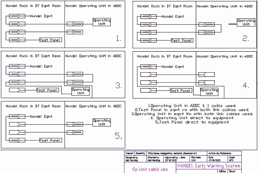
Some of the possible wiring configurations
Editor's notes, With reference to Neil's diagram above:
The normal condition.
Testing house wiring from equipment room with operating unit.
Testing house wiring from equipment room with test panel unit.
One of the two operating units plugged directly into the Handel equipment.
The last resort when both the normal operating unit and the reserve in cupboard don't work, so the test panel is used instead.
Neil explains:- 2 & 3 are testing from the equipment room with Operating Unit or test panel. Uses both cables so that the main connecting cable is included in the test. This scenario was used when it was not appropriate to be in the ADOC because it was in use by others and we could not risk conversations in the ADOC being overheard on the Handel test broadcast e.g. during the Falklands conflict.
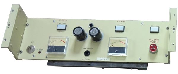
Unit WB1800/2A Rack Mounted Test Panel
Quarterly Testing of HANDEL
Carrier Control Points (CCP) were issued with three sets of instruction cards, Card 1 describes the Peacetime Testing Action, Card 2 for War Emergency Pre-Attack Action and Card 3 War Emergency Public Warning Action.
Card 1 gives details on how to respond to the tests of HANDEL and how to conduct the tests of the Carrier Receivers. The previous topic describes how those HANDEL tests were performed from the Injection Points. A member of the public happening to call the speaking clock at this time would have heard the innocent sounding test messages too.
The Carrier Control Card 1 'Peacetime Testing Action',
Section 2 reads : Handel Test will take place on the 1st Wednesday in January, April, July and October at 0200 hrs and 0215 hrs
Section 2.1 reads : Handel Pre-test action (to be carried out at least 10 minutes beforehand):- Lift both RED handsets. Listen to the Speaking Clock. Check audibility in both handsets. Now study the Handel Test report form in readiness for
Section 2.2 reads : When one or both RED lamps flash and alarms sound. Lift both RED handsets. Listen to the spoken message. Replace RED handsets. Note name of town mentioned.
Section 2.3 Complete the form 'Report on Routine Test on Handel Equipment' in duplicate at once and return it to Force Headquarters the same day.
$$
Speaking Clock Distribution Rings
To guard against failure of the speaking clock supply to telephone exchange, the two centres in Liverpool and London where the clocks themselves were located are linked together by two pairs of private circuits. These are different from those linking the HANDEL injection points in the diagram in the previous section.
Each private circuit carries the London clock towards Liverpool and the Liverpool clock down to London. This ensures that if one set of duplicated or triplicated clocks fails, those from the other centre are available throughout the country.
One of the private circuits between Liverpool and London routes via Birmingham, shown by the arrows in the diagram below. This carries TIM 3 and TIM 4 with TIM 1 and TIM 2 taking a different route between the two cities. Note: TIM = TIMe.
One of Many Speaking Clock Rings
The Liverpool and London Clocks are distributed via multiple small ring circuits around the main telephone switching centres. Under normal conditions every main switching centre has a feed from both clock centres. One example is shown on the diagram above, but there were many more rings. As well as feeding the speaking clock for the main exchange, both clocks were connected to the 250 Carrier Control Points.
In the Birmingham TIM ring shown above, it supplies HANDEL signal to Carrier Control Points (Carrier Area Number when known or XXX) at Stourbridge 091, Kidderminster XXX, Worcester 052, Hereford 053, Ludlow XXX, Shrewsbury XXX, Telford XXX and Wolverhampton 056.
The map shows Carrier Control Points 089 at Chelmsley Wood, 090 at Redditch and 092 at Walsall who would have received their HANDEL supply from a different TIM ring.
Carrier Control Point - Second Generation WB1400
The United Kingdom is divided into 250 Carrier Control Areas (CCA) each served by a Carrier Control Point (CCP) installed in a Major Police Station. Each CCP controlled the operation of Air Attack and Flood warning sirens and the broadcast by speech of the attack warning and subsequent fallout messages to warning districts within its local area. A list of Carrier Control Areas may be found using the quick link at the bottom of this page.
Block Schematic of Connections to a CCP
The block schematic diagram shows how two private circuits from the telephone exchange carry the speaking clock in one direction and the 72kHz carrier in the other. In the previous topic we read how the speaking clock circuits would be used to distribute the attack warning broadcasts. These duplicated private circuits take different routes to avoid a damaged cable isolating the CCP at the police station. At the exchange the two incoming carriers are monitored and one selected for distribution.
A third private circuit is for bothway communication with the UKWMO Group HQ. The UKWMO is responsible for issuing fallout warning messages and an all clear when the radiation has fallen to a safe level.
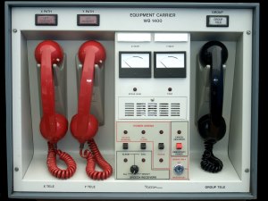
The small Equipment Carrier WB1400 control unit 21½"W x 11½"D x 17"H shown below performs the same function as much two larger WB400 control units in the police office and two steel cabinets, each 1ft 10in wide x 1ft 2in deep x 6ft high in the police station apparatus room containing all the logic and signal generation equipment.
Each of the three handsets terminates a pair of wires from the Control Point Exchange (CPE). The two Red handsets are designated "X Path" and "Y Path" and have associated Red "Lift Handset" lamps and alarm sounder. Providing there are no line faults both handset alarms sound in response to a broadcast message from Strike Command, lifting either will stop both alarms. The Red handsets can only listen to broadcasts as there is no return speech channel.
The WB1400 CCP$
The Black "Group" handset is for two way communication with the UKWMO Group Headquarters for the warning district(s) served by this CCP. When the U.K.W.M.O. Group calls the CCP, a white alarm lamp "Group Tele" and alarm sounder will continue until the black handset is lifted, or self cancel after 90 Seconds. To initiate a call to Group, the alarm lamp cover that also serves as a pushbutton is pressed, the local alarm sounds for the duration of the press.
The same two pairs of wires, the 'X' and 'Y' paths, used to bring the national warning to the Red handsets also return two separate feeds of the 72kHz carrier signal back to the Control Point Exchange (CPE). The carrier is modulated by either Police Officer's spoken messages or siren control signal. Mains fail alarms are signalled to the CPE over the 'X' and 'Y' path wires too.
In the CCP gallery, a close up shows the control switches on the CCP. The siren can only be activated when the "MASTER" locked rotary switch, located on the bottom right, is turned through 90° clockwise to the ON position. Verbal warning messages may be sent without the master switch being activated.
The two left hand keys are pushed upwards to initiate their respective siren activation "ATTACK WARNING" or "ALL CLEAR" sequence. The "CANCEL SEQUENCE" key stops an activation sequence before it has run its full course. The siren control signal sequence is heard through the grille above the keys. Remote siren receivers are controlled by a sequence of two audio tones, a guard or "G-signal" of 1500Hz and siren activation or "S-signal" of 2160Hz. To prime the siren receiver, the G-signal is pulsed twelve times of 0.4 seconds on and 0.4 seconds off. After the tenth pulse, the S-signal starts, its duration depends on the warning. For the Attack Warning, it is pulsed 4 Seconds on and 4 Seconds off or 60 Seconds continuously for the All Clear.
The same two keys pushed in a downward direction initiate a spoken broadcast to the warning receivers. The rotary switch under these keys allows either the "SELECT" group of receivers (Those used in ROC & UKWMO peacetime exercises) or "ALL" for every receiver (War Emergency and Police quarterly tests) to hear the message.
The sequence begins with either four (Select) or eight (All) pulses of 605Hz tone, known as the "W" signal which turns the receiver speaker on for at least 20 Seconds.
Next follows six seconds of either - rapid pips of the "CALL" sound - or the wailing of the"ALARM" sound.
After this, the "SPEAK NOW" light flashes for 7 seconds.
During this period either Red handset may be used to announce the message by pressing a small press-to-talk switch on the side of the handset. The "SPEAK NOW" light continues to flash during the message and for a further 7 seconds after the switch is released during which time a further message may be sent by operating the press-to-talk again.
Once the light stops flashing, it is necessary to operate either the Call or Alarm switch to make a further broadcast. Two modulation meters indicate to the operator the correct level for the spoken message. The needle should be within the thick black line area.
There is a difference between the terminology used on the CCP panel and the instructions. The ROC "Standard Operating Procedure, Annex P" refers to the four or eight "W" tones as the 'Call' signal. The CCP 'Call' signal of rapid pips is called the 'Alert' signal in the ROC operating procedure, and the CCP Instruction Card "Carrier Control Card 3". They do however agree on the wailing 'Alarm' signal.
Instructions for Operation in War$
The CCP Instruction Card telling the police officer how to use the panel in a war emergency is reproduced in the gallery above this text.
During periods when the CCP is not being used it modulates the carrier with a soft beeping 'Monitor Tone'. This tone can be heard if the warning point presses the test button on the carrier receiver's loudspeaker. It purpose is to give confidence the receiver is working properly. It may also be heard for a short time after the end of a spoken message, before the receiver speaker turns off.
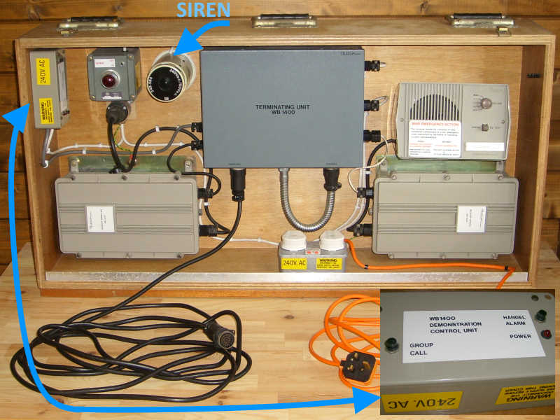
Carrier Control Point : Duplicated Control Units for Security
C.C.P. Installation
Two CCP control units in two separate locations are provided for security against equipment failure and damage. The ''Working' unit was located at the secondary location, normally an office environment. The 'Standby' control unit would be plugged in at the primary location, typically an equipment room or secure basement accommodation. The user instructions describe what to do under fault conditions. The cables between the secondary and primary locations are called the 'House Wiring' which is connected to the flexible lead exiting the bottom of the 'Terminating Unit WB 1400'
Extract from User Instructions
What to do if the normal control unit fails to indicate a confidence tick on both meters.
The 'Working' equipment is normally situated at the secondary operating location. Connect the equipment to the primary operating location 'Working' socket in place of the house wiring. If it then operates correctly the fault is in the house wiring and the equipment should be left operating at the primary location.
If the equipment still fails to operate connect the 'Standby' equipment to the 'Working' socket at the primary location. This equipment should then operate correctly.
Reconnect the house wiring to the 'Working' socket and install the 'Standby' equipment in the secondary operating position. It is important to inform British Telecom Fault Control if this action is taken.
Primary Location: Changeover Panel
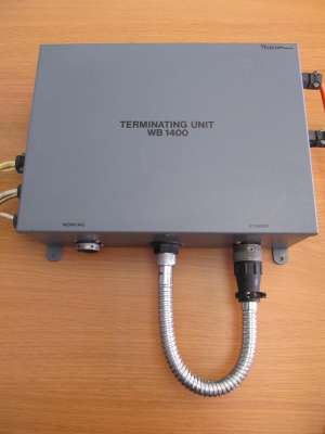
Terminating Unit WB1400$
The Terminating Unit WB 1400 is the hub of the system in the Police Station. Internally there are two power units which should be fed from different mains supplies to guard against a ringmain fuse blowing. Connection strips terminate the external wiring to the building's Main Distribution Frame (MDF) carrying the two HANDEL circuits and the UKWMO Group HQ circuit back to the exchange. Next to the power units are six test links (four red for HANDEL and two black for ROC) intercepting these circuits allowing BT to setup and test the CCP. Other connection strips terminate the internal cables to the Terminating Unit WB 1401 at the secondary location and the 100 hour reserve battery.
The reserve battery supply is only used if the mains fails. Housed in a wall mounted "Box Battery WB1400" it contains a "Terminating Unit WB1402" into which four "Battery Dry 101", rated at 18 volts, 20 Ampere Hour are wired in parallel. These are Lithium non-rechargeable batteries.
The flexible hose emerging from the bottom of the unit has a plug that is normally connected to the 'Working' socket. The reserve control unit's flexible lead is normally plugged into the 'Standby' socket. This may be changed around to isolate faults and maintain a working CCP.
Timings and Frequencies of Signals Generated by the CCP
The purpose of the various control signals generated by the CCP has been described earlier on this page. While the frequencies used and timing of these signals is of little interest to the casual reader of these pages, owners of WB 1400 receivers may be interested to see the Telecommunication Instruction E9 E3103 found in the Documentation Library on this website. See Section 4.5 & 4.6 on Pages 9 & 10
Police Routine Functional Test
The police carried out a routine test of carrier receivers at 3 month intervals. The test was performed at 0900, 1500 and 2000 hours. At each of these times, a short test of both the 'Call' and 'Warning' signal and a spoken message using a codeword the receiver owner wrote on a test form they must return to the police war duties officer, was repeated a total of five times at one minute intervals.
Tunbridge Wells Carrier Control Point
I am most grateful for the feedback received from Nick Ashdown in March 2012 for an actual recording of a WB 1400 test broadcast. I have reproduced an extract from Nick's email below. I find it incredible that two people have been kind enough to send me recordings of the same CCP but made decades apart.
EMAIL Extract
I was recently going through old cassette tapes and found the attached recording of a routine test from Tunbridge Wells CCP on our WB1400 recorded on the 29th of July 1987. I thought it would be a good comparison to the WB400 (we used to have one of these before it was swapped to the 1400) recording you have also from Tunbridge Wells.
Unfortunately my father died back in 1967, however we (My Mother) retained responsibility for the equipment and its routine checks up until it was removed in late 1987 (at our request). We also had a siren in its crate which we also tested once a year or so, not at full speed as we did not wish to alarm the villagers. I made the recording as we planned to ask for its removal and wanted to have something to remind us of the little box next to the phone by the front door. Very few people in the village new of its existence, when people visited, if they asked we just said ‘it’s something to do with the telephone.
Training Carrier Control Point Users
Two different kinds of training unit were made in very limited numbers. These were used for training police and BT Personnel in training schools, independently of the normal network, without the danger of setting off real sirens.
The version featured here, has a socket on the end of a flexible cable, into which a CCP console is plugged in. The training module can simulate incoming calls from the UKWMO Group HQ and a HANDEL message. As well as responding to siren signals and spoken messages.
Training Module Dgm. WB29876
Control Point Exchange WB1400 Era
In the block schematic, the Carrier Control Point CCP is connected via the three pairs of wires leaving the left hand side of the drawing. The thick double headed arrowed lines represent the external lines to the (CCP) located at the police station. The X and Y paths are routed in different cables for security against cable damage. Audio from the HANDEL interface goes towards the CCP. The CCP to group circuit is the third pair of wires shown.
CPE Block Schematic
The two speaking clock feeds and the private circuit to the ROC Group HQ enter the right hand side of the schematic. The carrier leaves the schematic at the bottom and feeds one or more distribution shelves, which send the carrier out on customers lines and onwards to other exchanges in the area.
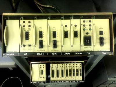
Gavin Saxby has kindly supplied the photographs in this section. The Control Point Exchange (CPE) consists of one control shelf (Equipment Carrier WB 1401) and one or more distribution shelves (Equipment Carrier WB 1402). The CPE shelves are fitted in the steel cabinet previously used by the WB400 CPE. The cabinet is cabled back to a connection block on the telephone exchange's main distribution frame, where all the external circuits are connected.
Looking down from the top of the cabinet the CPE interface shelf is at the top and a distribution shelf below it. Each shelf holds a number of slide in units, each type of "Unit WB1400" is identified by a stroke number. To ensure the correct slide in unit is fitted in each position, its stroke number is engraved along the bottom of the shelf.
Inside the CPE Cabinet$
Each HANDEL interface (Unit WB 1400/1B) amplifies the audio from the speaking clock in the direction of the CCP. It detects a 1200Hz plus 1440Hz P+Q signal lasting for more than 1 second sent immediately before the Attack Warning message and converts it into a 180Hz signal of 711mS duration to alert the CCP. A filter blocks the carrier coming back from the CCP over the X and Y paths from the audio amplifier.
The carrier from the CCP is normally received along both the X and Y paths. A preamplifier (Unit WB 1400/2B) in each path monitors the carrier, if it fails, a signal is passed to the changeover unit (Unit WB 1400/7B). The changeover unit returns a signal selecting only one of the pair of pre-amplifiers to turn its output on. Should one path fail the other path is automatically selected. A manual changeover button is also provided for maintenance staff. The changeover unit raises an alarm should either or both carriers fail.
The two CCP power units extend a signal over the X and Y path to indicate their health. This too is monitored by the changeover unit and an appropriate alarm raised on failure. If both fail it is assumed the CCP is running on batteries, the duration is recorded on the resetable meter.
The line between the CCP and the UKWMO Group HQ is routed via a signalling converter (Unit WB 1400/10A) when Group calls the CCP, the balanced battery signal from Group is converted to 25Hz ringing towards the CCP. The CCP calls Group by placing an earth on its B-wire only, the converter sends balanced battery to call Group Headquarters. Whereas the HANDEL circuits are unidirectional, the line to the Group works bothways for speech and signalling.
The CPE shelf power is supplied by the Unit WB 1400/8B and is derived from the telephone exchange -50 volt supply with a 1000 hour reserve in the form of Lithium Chloride batteries in the box below.
East Kilbride CCP and Receivers : A Working Example
East Kilbride Records
The gallery contains a selection of the original record cards from East Kilbride, a town located on the south east side of Glasgow. The records represent only the Control Point Exchange (CPE) and the receiver points associated with that exchange only. There are carrier feeds to three nearby exchanges which have their own receiver points. I am most grateful to Mike Scott for this information that he gathered during the creation of the HANDEL display at the Dundee Sector Museum which utilises the old East Kilbride CPE rack.
Every Carrier Control Area ( CCA) has a three digit code number, East Kilbride CCA is 233. All receiver points bear this number followed by a slash identifying the individual feed. The letters EFI appear on a number of records, this is the internal code for East Kilbride Exchange. The whole of a Carrier Area is recorded as PW 103xxx, where xxx is that 3-digit code. East Kilbride is PW103233 but I don't have the whole CCA drawing, however further down the page in the "Carrier Distribution between Exchanges" topic is a drawing for the whole of the Swansea CCA, PW 103036. There is no information on Swansea's receiver points available.
The gallery images are explained below.
Google Earth view of Receiver Points, Red = Siren Receivers, Green = Speech Receivers, Orange = Both Siren and Speech Receivers served by East Kilbride exchange.
Google Earth view of Exchange (CPE), Firestation and Police Station with the CCP and Receiver point 233/1 having both speech and siren receivers.
The CPE Record Card A526(a) showing the incoming terminations from the CCP and the outgoing carrier paths to Rutherglen, Busby and Griffnock exchanges. The CCP has two feeds, the X and Y paths.
The reverse side of the A526 card showing the Distribution Amplifiers and Local Line Units used for each receiver point. In receiver point order.
The Station Record A741(a) showing the receiver point number, location and bearer used for carrier feed.
Reverse side of A471, showing more receiver points.
Equipment Provision A403(a) Same data as A526 above, but seen from the Distribution Amplifier point of view. 1 of 2
Equipment Provision A403(a) for another Distribution Amplifier shelf. 2 of 2
Fault Record Card A2699(a) recording faults seen from the perspective of speech receiver 233/90
Fault Record Card A2699(a) recording faults seen from the perspective of siren receiver 233/12
Fault Record Card A2699(a) recording faults seen from the perspective of 233/5, where there are both a speech receiver in the Stationery Store and siren receiver in the mains switch room, as the siren control panel has to be close to the incoming mains supply. At locations with a single phone line serving both receivers, then an arrangement described on the WB1400 Part 2 page in topic "Special Cases Preventing Fault Monitoring from the Local Exchange" will be needed.


 This page is Copyright © RINGBELL.CO.UK, under a


