The history of the U.K. Police and Fire VHF Wireless systems pre-1987. Although not part of the UKWMO communications or Regional Government system the Countywide VHF Emergency Service radio would have played a part in the post strike recovery process. Regional Government Headquarters had access to these systems.
County Wide VHF Radio Schemes
In this simplified diagram a hilltop is connected to the control by two radio links. When the control room operator speaks, the link transmitter A turns on and sends the voice message to the hilltop. The presence of a signal on the radio link operates a relay in receiver B that turns on the main transmitter C. The audio output from link receiver B is connected to the audio in on the main transmitter. When the mobile replies, its signal is picked up at the hilltop by main receiver D which operates a relay that turns on link transmitter E. Link receiver F receives the signal and operates a call lamp and the audio goes through to the operator's handset in the control room.
Basic Hilltop Relay
In order to facilitate good quality communications across the whole of a UK County at VHF it is necessary to employ a number of hill top relays. In my home county of Northamptonshire, which is relatively flat, two sites about 30 miles apart provided the necessary coverage. Other counties that were larger or had many hills and valleys required more sites. Each hill top site is linked to the control room by a pair of radio links. Using more than one radio site presents a number of technical challenges that have to be solved.
Two Hilltops Relaying to one Control Room
In the outgoing direction, when the control room operator speaks, two or more transmitters will radiate the signal on the same channel. Depending on its location, a mobile receiver may pick up more than one signal. Too avoid creating a heterodyne whistle distorting the spoken message, the transmitters radiate on frequencies offset from the nominal channel frequency, by an amount that causes the heterodyne to be outside the 4kHz audio bandwidth of the receiver.
Multiple Offset Carrier Frequencies on a Single Channel
In schemes with two hilltops, carriers were offset by +3kHz and -3kHz causing a 6kHz heterodyne. With three hilltops offsets of -9kHz, +3kHz and +9kHz, created heterodynes of 6kHz, 12kHz and 18kHz all outside the 4kHz bandwidth of the receiver. More than three sites transmitting simultaneously was to be avoided due to the difficulty in filtering out the heterodyne whistles.
In the incoming direction the problem is not quite so easy to solve. A mobile at position A will present a good signal to hilltop site North and no signal to hilltop site South. Only the North hilltop will relay the mobile user's voice to the control room. A mobile at position B will present a good signal to the South hilltop site and a poor signal to the North hilltop. Both sites will relay the mobile user's voice, but the control room will hear the combination of both the good and noisy signal, so may have difficulty in hearing the mobile.
PYE Assort Voting System
Pye Telecommunications in Cambridge, England, designed a solution to the incoming signal problem and marketed it under the name ASSORT an acronym for 'Automatic System for Selection of Receiver and Transmitter'. Their solution was to transmit a signal in the audio channel from the hilltop to the control room that represented the strength of the received signal at the base receiver. An additional circuit board fitted in the base receiver measures the signal strength and generates a 'quality' tone between 2700 - 3000 Hz, representing the strength of the received signal and hence its audio quality. The stronger the signal the higher the tone frequency. The tone is removed when the receiver squelch closes.
At the control room, the ASSORT equipment examines a maximum of sixteen incoming links and dynamically selects the audio from the basestation receiving the strongest signal. If the mobile is moving during a transmission, the audio heard by the control operator is seamlessly switched from site to site. A filter prevents the operator hearing the ASSORT tone. In their 1971 literature, Pye claimed to have installed a scheme in Paris with twelve remote sites.
Radio Link Assembly
Pye Telecommunications was awarded a contract by the Home Office to supply standardised Hill Top sites and control stations using their ASSORT system known as the 'Radio Link Assembly' ( RLA ).
The main features of the Radio Links Assembly are.
- Duplication of all parts of the system.
- Connection of a maximum of 5 hill top sites.
- Remote control of switching of the duplicated equipment from main to standby.
- Signalling hilltop fault conditions to control station.
- Two of the hilltop sites may be indirectly connected via another standard hilltop.
- Keying of individual hilltop main transmitters.
- Selection of the strongest received audio using the ASSORT system.
Radio Link Assembly Block Diagram
The outgoing radio link from the control station to the hilltop radiates continuously. This carries a number of high frequency tones, one per hilltop, just above the normal range of speech frequencies but audible on a scanning receiver. Each tone is shifted upwards in frequency by 60Hz to activate the selected hilltop. Normally all hilltops are activated but the control has the facility to inhibit a site. The multiple high frequency audio tones gave a distinctive signature to the link channel.
Transmitter Activation Tones [120Hz spacing]
Site
Nominal Channel Frequency
Standby [n-30Hz]
Active [n+30Hz]
A
3300Hz
3270Hz
3330Hz
B
3180Hz
3150Hz
3210Hz
C
3060Hz
3030Hz
3090Hz
D
‡2940Hz
2910Hz
2970Hz
E
‡2820Hz
2790Hz
2850Hz
‡ Calculated.
At the hilltop both link receivers operate in parallel. A filter removes the activate signals from the audio going forward to the duplicated main transmitter so they are not heard by the mobiles. The two main transmitters are configured in a 'Working' and 'Standby' mode. The currently 'Working' transmitter is keyed in response to the site's individual control tone shifting to the activate frequency.
The radio link from the hilltop towards the control station radiates continually. A link pilot tone of a nominal 3300Hz is sent over the continuously operated link transmitter. When no mobile is transmitting only this pilot tone is heard on the link channel.
At the hilltop, failure of one or both incoming link receivers is signalled back to the control station by using the link pilot. If both of the duplicated link receivers fail to receive a signal from the control station, the hilltop link pilot changes from the usual OK; 3270 Hz to FAIL; 3330Hz tone. Failure of both receivers could be due to a fault at the control station preventing it sending its outgoing signal, an aerial or feeder fault at the hilltop, or both hilltop receivers' electronics failing. Under these conditions the hilltop site switches to local talk through independently of the control station. Any received mobile signal is relayed back out via the main transmitter. This would allow mobiles in the vicinity to communicate with each other. If just one incoming link receiver fails, or another less serious problem occurs, it is signalled to the control station by switching the link pilot tone between the OK and Fail tones at 0.5 second intervals.
The main hilltop receiver incorporates an ASSORT signal generator, which adds a signal quality tone between 2700Hz and 3000Hz to the received audio being sent to the control station. The stronger the received signal from the mobile the higher the ASSORT quality tone frequency. This quality tone is removed when no mobile is being received.
At the control station each link receiver is fed into the ASSORT voting comparator which uses the quality tone to select the audio from the hilltop with the strongest signal. This voting process is repeated 10 times a second to allow for changes in signal as the mobile moves. A low pass filter in the comparator removes the quality tone and link pilot from the audio sent to the control room, so the operators do not hear it.
To enable fault conditions to be isolated all duplicated equipment can be individually changed from Bay-A to Bay-B or the other way around. This may be done from the control rack in the radio room at the control station or from within the control room. The remote control of the hilltops is done using dual frequency in-band signals resembling telephone keypad tones. Combinations of tones are used to separately change Main Tx, Main Rx or Link Tx to the other bay, change the whole site to the other bay, or clear all changes. The hilltop link receivers can't be changed over, as potentially a faulty standby link receiver would result in the loss of the ability to switch back again, if it were selected as the 'Worker', therefore both link receivers must run in parallel. At the control station each returning link pilot is monitored to detect remote site faults.
Should the control station fail, all hilltop sites switch to local talkthrough enabling mobiles to talk to each other. The control station is able to join the Net as a mobile using a separate transceiver provided for this emergency situation. When lightning struck the tower at West Midlands Police HQ during a snow storm in 1991, knocking out all the radio links, the control room had to join the net as a mobile. The computers were affected too, so they had to rely on scraps of paper, to record the position of the vehicles. The heavy snow blocked the M6 through the Midlands and people were trapped in their cars all night - it was chaos!
Police Controls normally operated their radios in piptone mode. When the mobile starts transmitting, pip tones are sent out from the control. These are removed when the controller presses the push to talk switch and restored again when it is released. At the end of the message exchange the control would sign off and remove the pip tones. If two mobiles wished to talk to each other, the operator selects talk-through mode. The best quality audio signal from the mobile selected by ASSORT, is sent back out to all the hilltop sites. Fire authorities preferred to operate their radios with talk through permanently switched on.
Lincolnshire Fire [1980]
The diagram illustrates how Lincolnshire Fire used the Radio Link Assembly in 1981. The frequencies shown in the diagram are those I noted down during my tracing of the ROC radio links. At that time the fire control was in the heart of Lincoln, the mast was not very high and I have to assume couldn't get a good radio link to the Kirkby Underwood hilltop site so it was indirectly connected using Fulletby as a relay.
The control room transmitted its messages to mobiles on 147.525MHz to four masts, Fulletby relayed this to Kirkby Underwood on 155.350MHz. All five sites broadcast the control room on 98.900MHz. Mobiles replying on 83.85MHz were relayed back to the control room on their own specific frequency. In the case of Kirkby Underwood the mobile to control room link frequency 146.225MHz was received at Fulletby and retransmitted on 154.350MHz, while it relayed its own mobile signal on 154.175MHz.
Main Channel Frequencies
Prior to the conversion program to align Emergency Service radio frequencies with the 1979 World Administrative Radio Conference (WARC) decision, the Main transmitters at the hilltop site used the bands 97-103MHz and the Mobiles 80-85MHz. The list below shows a number of schemes in the Midlands, where I happened to discover both the fixed and mobile frequencies, these are supplemented by reader's feedback.
Base Transmit Order
Base TX
Mobile TX
Callsign
Channel
97.900
81.825
M2MA
West Midlands Police Ch6
97.950
82.650
M2YM
West Midlands Police Ch4
98.050
82.750
M2NG
Northants Police Ch1
98.075
82.225
M2NG
Northants Police Ch2
98.250
82.950
M2VK
Norfolk Police
98.325
82.575
M2YK
West Mercia Police
98.350
83.050
M2VG
Essex Police Ch1
98.425
82.675
M2YK
West Mercia Police
98.450
83.150
M2VG
Essex Police Ch2
98.700
82.600
M2YM
West Midlands Police Ch3
98.725
82.925
M2VG
Essex Police Ch3
98.775
83.325
M2VB
Cambridgeshire Police
98.825
82.475
M2YM
West Midlands Police Ch2
98.875
82.325
M2YM
West Midlands Police Ch5
98.900
83.850
M2NV
Lincolnshire Fire
98.950
83.650
M2MP
Met. Police Ch2
99.400
82.050
M2YM
West Midlands Police Ch1
99.850
82.250
M2VI
Hertfordshire Fire
100.100
82.250
M2VN
Suffolk Fire {‡ 100.775}
100.150
82.650
M2VD
Essex Fire {‡ 100.825}
100.200
83.775
M2VC
Cambridgeshire Fire
100.250
82.600
M2VH
Hertfordshire Police
100.400
82.800
M2VL
Suffolk Police
100.425
83.675
M2FB
West Midlands Fire F.B.Whiskey
100.475
83.650
M2FB
West Midlands Fire Ch1
100.600
83.475
M2FB
West Midlands Fire F.B.Echo
100.625
81.950
M2FH
London Fire Brigade
100.850
83.250
M2FB
West Midlands Fire F.B.Xray
100.925
82.400
M2YF
Staffordshire Police
101.200
83.950
M2YG
Staffordshire Fire
101.225
83.425
M2MP
Met. Police Oscar
101.350
82.300
M2YF
Staffordshire Police
101.550
83.125
M2YJ
Warwickshire Police
101.600
82.525
M2NO
Northants Fire
101.650
82.300
M2NL
Leicestershire Police Ch1
101.700
81.800
M2NL
Leicestershire Police Ch2
101.900
83.625
M2YJ
Warwickshire Police
101.950
82.350
M2KA
Kent Police
‡ Moved to this new frequency to avoid continental interference.
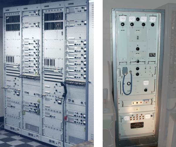
Radio Equipment Hardware
Radio Link Assembly : Hilltop Main Transmitter
The left-hand photograph above (Courtesy of Martin Swift) shows two sets of Radio Link Assembly, each serving a channel at a Main Station (2 Racks per channel), each RLA serves three remote hilltop sites. The right-hand rack in each assembly contains two link transmitters and six link receivers, providing duplication of transmitter and receivers.
The Police and Fire Main Transmitter at hilltop sites were often 250 watt AM transmitters similar to the right-hand photograph taken at Hack Green Museum. These too would be duplicated to guard against failure. In contrast Private Mobile Radio base stations were usually limited to 5 or 10 Watt transmitters.
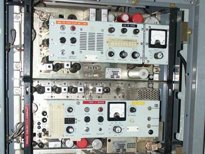
Thermionic Valve UHF Link Equipment
The photo taken at Hack Green Museum shows a valve operated UHF link receiver (top shelf) and link transmitter (lower shelf). Each is mounted on its own chassis with space for 4 chassis per 6 foot rack and predate the RLA. These are the type used for the RGHQ links at UHF and some fire services who used links in the UHF bands rather than the normal VHF links.
![Lincolnshire Fire [1980]](img/lincfire.gif)
 This page is Copyright © RINGBELL.CO.UK, under a