This first of two pages documents the Air Raid Sirens used in Great Britain during the Cold War period. Three different makes of siren were approved by the UK Home Office. A trial of two pneumatic sirens took place but were not adopted for use.
I am indebted to James Sansom and Paul Lawrence for providing the majority of photographs on this page, hopefully with its sister page, making it one of the most comprehensive sources of United Kingdom air raid siren information on the WWW.
The Siren
Sound is transmitted to our ears in the form of pressure waves often created by the vibrating surface of the object making the noise. This may be a piano string or skin on a drum. The siren creates sound pressure waves by rapidly releasing bursts of high pressure air through small openings.
Rotary Siren
The siren has one or more fans rotating at high speed, causing air to be forced outwards by centrifugal force, creating a high pressure at the impeller's circumference. The high pressure air is unable to flow continually due to the chopper projections at the end of the blades. There are an equal number of blades and holes in the sound box. Air can only escape when the choppers uncover the openings in the surrounding sound box.
Typically, a British air raid siren rotates at 2850-2900 revolutions per minute, one end has 10 openings and 10 blades, the other has 12 of each. This creates two tones harmonically related to each other as a minor third. The tone in Hertz can be calculated by multiplying the rotation speed in R.P.M. by the number of openings and dividing by sixty.
For example, at 2850 r.p.m. the two tones are 475 Hz and 570 Hz.
UK Air Raid Siren Types
There were a number of different sirens dating from WW2 that continued to be used for Civil Defence purposes. The Siren No. 1/L manufactured by Gent & Co, Leicester, who called it a 'Syren'. The Siren No. 1/S manufactured by Service Electric Ltd Stanmore. The Siren No. 1/N manufactured by Carter (Nelson) Ltd of Nelson Lancs, Carter later became Castle Castings of Clitheroe Lancs, who produced sirens during the Cold War period.
On the second page of this section, the "Siren Station Planning Document" refers to these siren codes on its top right hand corner. The Secomak siren in the gallery has the Home Office code 1/S stamped on its motor rating plate.
Gents' Syren
No this is not a spelling mistake, but the alternative mainly British spelling, adopted by Gents. A siren was a Greek Mythical creature that lured sailors to their death with wailing noises.
Gents' Syren Gallery
In the gallery above, Paul Lawrence provided the first three images of a restored "Gents Syren". Jason Miles kindly supplied the disassembled views. Adam Bennett, the Gents' pamphlet (of WW2 vintage) providing planning guidance on matters including sound range, use of sound deflectors, wiring for different types of mains power supplies.
Castle Castings
James Sansom has kindly provided five photographs of his restored Castle Castings siren, which can be identified by the CC on the fan blades as well as the main motor label.
Castle Castings Siren
Paul Lawrence is credited for the additional disassembled view, a nineteen fifties version of the Castle siren with a different motor (featuring a rounded shape of junction box) and finally a Castle with a single phase motor and capacitor standing alongside but not yet wired into circuit.
The single phase motor is noticeably larger than the 3-phase version and consumes as much current (22A) from its single supply line as the 3-phase shares across all three lines (7.2A each). The induction motor has a single main winding with a capacitor fed auxiliary winding.
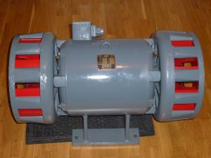
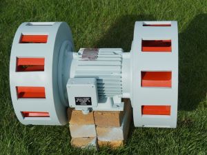
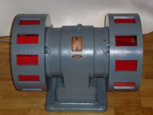
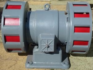
Carter Siren
I am very grateful to Paul Lawrence for his photographs (1 - 3) of a restored 'Early' period Carter siren which is similar to the WW2 design but the fan housing is cast aluminium. Close inspection shows concentric grooves on the fan housing. In the third image, the small balancing holes drilled into the bottom of the fan assembly to stop vibration can be seen.
Carter Siren
The final three photographs in this gallery show a partially restored Carter from the later Cold War period. It has been shot blasted and red primed ready for the final colours of a grey body and red blades. It has motor cooling fins and different shaped junction box compared to the earlier version
The WW2 Carter can be distinguished by a totally different two hole mounting base, no lifting eye and its fan housings are made from cast iron and are not grooved like the cold war version.
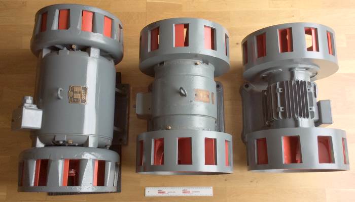
Comparative Sizes of Sirens
Gents Carter Castle
The Gents, Carter and Castle can be seen standing next to one another with a 30 cm / 12" ruler below them to give an idea of the comparative size and scale of the different siren types.
All designs comply with the Home Office specification for a 4-5 h.p. siren but their output ratings vary by manufacturer. The horsepower (h.p.) is an imperial measurement of power output, where 1 h.p. = 746 watts (0.7457 kW)
Service Electric SECOMAK Siren
Paul Lawrence explains in his notes accompanying his photos, that at first glance, the Secomak Siren is very similar in appearance to the Carter design.
Service Electric / Secomak Siren
There are subtle differences in the sound box holes. The Secomak has chamfered holes whereas the Carter doesn't. The fan blades are different in design. In the second gallery photograph, countersunk screws on the righthand side of the fan hold small balancing weights in place. Carter fans are balanced by holes drilled in the assembly.
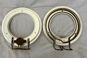
Siren Defrosting Heater Units
Siren Heaters and Thermostat
To prevent the siren fans freezing with ice and snow, each end has a 1000 Watt heater, with an element similar to those in an electric kettle. These are controlled by a thermostat mounted near to the siren.
The first photograph in the Gallery shows two new heater units. The second are the heaters removed from a siren but still connected together with electrical conduit.
The gallery includes four photographs of an original thermostat, showing the outer box closed and opened to reveal the thermostat. The bimetal strip and contacts are inside the curved black plastic moulding. On the rear of the moulding are two resistor coils, these are used to reduce the thermal hysteresis (the difference between turn on and turn off temperature) of the thermostat. This is a common technique used on mechanical thermostats including domestic devices. Modern electronic thermostats suffer from the opposite of this problem, so the controller has increase the hysteresis to avoid the heater / boiler switching rapidly on and off.
The final photo in the gallery is a later design of mechanical frost stat encased in a weatherproof box. The temperature was found to be set to 1°C.
$$$$$
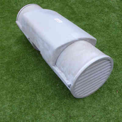
Weatherproof Siren Casing
Some sirens were enclosed in Glass Reinforced Plastic (G.R.P. / Fibreglass) covers to protect them from the elements and nesting birds.
Glass Reinforced Plastic Siren Cover
The siren is mounted normally, with a seven part casing clamping around but not bolted to its body. The siren sits under the central oblong shaped cover with its motor section exposed for cooling. Each fan is enclosed in a two part extension tube, this is long enough to fit over flaps, should they be fitted. The upper half of the tube is solid GRP to exclude the weather and the lower part louvered to let the sound out. A louvered end cap completes the casing.
$
Compressed Air Siren Field Trial
I am very grateful to Joachim Schmidt for drawing to my attention a Home Office file in the National Archives, Kew relating to a field trial and proposed rollout of compressed air sirens across the UK. The file runs to 67 pages and contains lots of technical details, so I have summarised it below.
Having recognised the deficiency of the present system of hand sirens in rural areas and mains operated sirens in towns and cities, enquiries were made worldwide. The only known equipment to meet all the Home Office's requirements were the compressed air sirens extensively used in Germany.
A siren from each of two suppliers were installed in the Harrogate area and trials took place in November 1969 and April 1970 which confirmed the findings of the German government that the sirens had a range of about 3½ miles. This would require the sirens to be set out on a 5 mile grid. It was estimated that 2000 sirens but probably less would be required. These would be installed over a 10 year period at a cost of £12M.
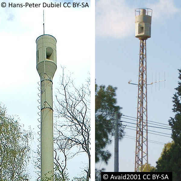
Pintsch Bamag : Hörmann
This type of siren has a compressed air tank topped up by an engine driven compressor, so it is always ready to go. The siren head at the top of the mast has an electrically operated valve to control the on / off period of the sound. An electric motor whose speed can be varied drives a perforated disk to modulate the air flow and produce the sound via four horns.
A test of a restored pneumatic siren in Nussdorf, Bavaria can be seen and heard on YouTube.
For more information about the locations of compressed air sirens in Germany and an explanation of their technology visit www.hochleistungssirene.de Follow menu Technik / Funktion for many photographs of the Pintsch Bamag siren.
Deficiencies of Present System (circa 1970)
The archived Home Office document WMO/69 14/5/12 in the National Archives [WORK12-932] says there are approximately 7,000 Electric Sirens in areas with population density of 3,000 per square mile, and 13,000 Hand Sirens in areas with lower population densities. Something less than 90% of the population is within hearing distance.
It describes the warning systems in use in the early seventies focussing on their shortcomings.
Electric Sirens These have a range of ¾ to 1¼ miles and are dependent upon public power supplies. They could not therefore be relied upon to give other than the initial RED warning and if an attack on this country was launched from outside the surveillance of the BMEW system, even this warning could be placed in jeopardy through disruption to the public power supply. Further, a large number of sirens are old, as they were manufactured before or during the last war: their condition is suspect to the extent that, in the interests of public safety, sound trials of the warning system have been discontinued until they are replaced.
Hand Sirens The initial distribution of hand sirens to the police was completed in 1967 and tests carried out in 1968, established that the range of these instruments was considerably less than had been assumed when rural coverage was originally planned. Furthermore, the physical effort to produce the necessary volume of sound for the required period of one minute is beyond the capacity of anyone but a very strong and fit person. To provide additional sirens on a scale sufficient to give effective warning coverage would be uneconomical.
Maroons These are an effective warning instrument but they are complex and sensitive pyrotechnics and present many storage and transport difficulties. Because of storage difficulties these instruments cannot be distributed to warning points until immediately before the onset of an emergency: this places an unnecessary burden on the police, who are responsible for warning points. Also a certain proportion need to be proof-fired at regular intervals - thus reducing available stocks - at an estimated cost of £50,000 annually.
The existing warning equipment is limited to giving two warnings only, and the all clear; if a warning of biological and chemical threat were required modification of existing equipment, or additional equipment, would be necessary.
The file goes on to cite how changes to policing will also affect the warning systems.
A further general complication which is giving grounds for concern is the introduction of unit beat policing and the consequent closure of many rural police stations, present designated as warning points: this, coupled with the likely withdrawal in an emergency of the remaining rural manpower into urban areas, would seriously diminish the number of warning points, particularly in rural areas, which could be established in official premises. To re-site these public warning points on private premises, which would be the only alternative, manned by members of the public whose reliability in an emergency must always be suspect and whose training places a considerable burden on the police, would be a retrograde step: the problem of testing the carrier equipment at these warning points in peacetime would be magnified.
Advantages of Pneumatic Sirens
The next paragraph really tries to sell the pneumatic siren as the only alternative
The compressed air siren A recent study was directed to finding a piece of equipment which would give the full range of warnings required, including additional warnings - should this be necessary - in connection with biological and chemical warfare. Ideally the equipment should work independently of public power supplies. With the assistance of an acoustics expert at the National Physical Laboratory, and Scientific Advisory Branch, and in consultation with other bodies whose business is to warn (e.g. Trinity House), the only known equipment (after extensive enquiries in Europe, USA and Japan) suited our needs was a compressed air siren already extensively used in Germany; and although developments in the technological field of sound propagation are being kept under review, this appreciation remains currently valid.
The Outcome
The file ends before the decision is made about a rollout of the compressed air sirens. We do not know the reason why, but hindsight tells us it did not happen, most likely due to costs. Where necessary, old WWII electric sirens were replaced with modern ones, so too were the maroons. Despite the shortcomings noted in the archive file, hand operated sirens continued to be in service until the end of the cold war and many warning points remained located in private premises.
It is quite disgraceful that the siren system was not audibly tested between 1966 and the end of the cold war, even though the UKWMO and Home Office were very aware that it might not work. Tests on flood sirens had highlighted all manner of dormant faults. This sad story described in detail further down this chapter.
Audible Testing of UK Air Raid Sirens
Correspondence in the Home Office archive file HO393/63 is very enlightening. During a test in 1966 a siren somewhere in Scotland broke apart showering metal in all directions. Consequently a letter to all Chief Constables, dated 12 December 1966 suspended all audible testing pending further investigation.
The problem was found to be due to the holes drilled for fixing the heater plates causing cracks in the sound box. Siren reseller, Paul Lawrence suggests this might have been a Gents siren as he has experienced this type of cracking in it's cast iron sound box.
A letter in August 1967 refers to the letter in December 1966 saying examination of a sample of sirens suggests any wartime or pre-war sirens are suspect and must be replaced. An arbitrary deadline of 31 December 1946 was set (pre-1947) for those sirens that needed replacement.
12 years later. A letter to the War Duty in each police force dated 23 March 1979 reads: As you may know in recent years sound testing of power-operated sirens has been restricted to a 6 monthly maintenance check (known as a "flick test"), sufficient to cause the siren to "run up" but not "to voice", in order to avoid the risk of accident from metal fatigue pending completion of the planned replacement of pre-1947 sirens.
About 1350 new sirens have already been installed in lieu of time expired equipment. This Headquarters proposes to reconsider the position having regard to the number and whereabouts of remaining pre-1947 sirens at the end of the current financial year with a view to the reintroduction of audible testing of sirens as soon as possible, except in Carrier Areas where those old sirens still exist, in order to determine both the adequacy of sound coverage and the real operational state of readiness of the WB600 siren system. . . . The archive contains many replies to this letter.
Moving on to 20 August 1984, the archive file contains a letter to Mr. W P Lawrie, Deputy director of the UKWMO from the Midland Sector controller, at Fiskerton. This kicks off a series of letters regarding the periodicity, timing and reasoning behind the resumption of audible testing. The letter has a little poke at the President of the United States, Ronald Regan (1981-1989) who had joked earlier in that same month during a microphone test about bombing the Soviets. There is no reason why such annual tests should cause any great public concern unless of course the siren sounding happens to coincide with one of Mr Reagan's witty remarks about bombing the USSR in five minutes time.
Views are sought from police forces across the country, but its clear there is little consensus. By now in the mid-eighties the old WB600 system was being replaced by WB1400. Some suggested that tests be delayed until the WB1400 was in place. There was debate as to whether hand sirens should be included.
File Item 51: is a letter from Kent, in favour of a full test as the only way to ensure the whole system functions correctly. This cites a flood siren test on 24/9/85. All sirens responded to the flick test, but when a full test activated from the CCP took place only 1 of 5 sirens functioned correctly.
File Item 85: A letter from Mr Walley in the Home Office dated 5-May-1987 contains the following paragraph 2. I entirely accept the logical argument that if our system of warning relies upon audible sirens, we ought to establish as clearly as we can whether they would do the job expected of them. It cannot be satisfactory that they have not been fully tested since 1966.
File Item 95: A covering letter and a Draft UKWMO Explanation for the resumption of siren testing, dated 14-August-1987. This document gives an insight into the cost of the warning system. 6. maintenance of the siren system is a major continuing expense, some £3 million per annum at present. In addition, expenditure on new carrier circuitry (known as WB1400) from and including the CCPs is costing a total of £24.6 million between 1982/83 and 1987/88. These are major expenditure commitments, reflecting the importance of being able to warn people to take cover from an impending air attack.
7. Given the level of expenditure and the inability adequately to demonstrate that the system work, it is essential that some form of audible testing of power sirens is undertaken before they may be required in wartime. . . . Given the above facts, one might assume testing would resume. The document says that current models of hand-sirens have limited range and a suitable replacement is needed, so they won't be tested.
The last document in the archive is dated 9-September-1988. At this point, the Home Office still have not taken their plans for ministerial approval.
In hindsight we know that the siren system was never audibly tested (see Note) between 1966 and the stand down of the UKWMO in 1991, despite a huge sum of taxpayers money being spent on its upkeep. Judging by the feedback to the UKWMO about the problems with flood sirens being faulty on test, it is safe to assume air raid sirens would have been no different. The power siren relied on the continuity of the electricity supply, which could not be guaranteed in a war situation. In the late sixties, the hand siren was known to be ineffective, but not replaced. For unknown reasons the program to roll out compressed air sirens, which would have overcome both these shortcomings, did not proceed.
Note: Air raid sirens may have been briefly heard during their regular electrical inspections and possible by GPO Engineers, who like the author performed a 'flick test' after changing the remote control equipment. Power was applied to the motor for less than a second, never getting up to full speed and consequently decaying within roughly 10 seconds. They were not tested from end-to-end by operating the 'Raiders Passed' siren key at the Carrier Control Point after 1966.
Locations of Power Sirens
Frequently over the life of this website people have enquired about the location of power operated sirens. I have been unable to answer their queries as no national records were kept but each Police Force was responsible for the sirens within their area.
In the days before fire fighters had radio pagers in the seventies, retained staff were called to the fire station by bells in their houses and the sounding of the siren at the fire station. As well as calling fire fighters to man the appliance the siren had joint use for civil defence. After their use by the fire brigade was replaced by radio alerters these sirens were kept for civil defence use.
Essex
Sue Burden has kindly supplied this list of power siren locations in Essex, most of which were removed after 1991. Additionally there were hand operated sirens at ROC Posts and Carrier Warning Points.
Bocking Churchstreet TL759260 Just behind the village hall, seated on 2 horizontal metal bars between 2 wooden poles. Site has been built over by an extension to the Village Club entrance porch.
Braintree, Fire Station TL757232 Stood on the rear left corner of the building. Around 1989- 90 a new fire station was built at TL752230, and a siren was placed on the drill tower, on a mount quite near the top. I do not know if it was the same siren, or if they acquired a new one. The old fire station building exists, but greatly heightened, obliterating the siren site. The mounting for the siren at the current fire station can still be seen on the west side of the tower.
Broomfield - Broomfield Place TL706099. Large early 19th Century house, which had a siren mounted on the chimney. The house was sold by the family to Essex County Council after 1942, but the Council sold it on some time after 1988. A PDF exists online about the history of Broomfield Place, and the siren can be seen in one of the 1974 photos.
Leaden Roding TL596135 Fire Station The siren was mounted on the right rear corner of the building, as this fire station has no drill tower.
Witham TL821153 The Crittall Windows factory, which stood by the railway line, had a siren mounted on the top. It was demolished circa 1996.
Wivenhoe TM040232 This fire station actually still has a siren mounted on the drill tower, which is tested from time to time. After the end of the Cold War, the County Council retained a number of sirens in coastal areas, to be used for flood warnings. Almost all of these were removed in more recent years to save money, with the assumption that flood warnings would be sent by text. Wivenhoe is a coastal town, but the fire station is set back from the sea on top of the hill.
Staffordshire
Werrington (Caverswall) SJ942475. The windmill tower here was turned into an OP for the Home Guard in 1940. I assume it has a concrete flat roof, as on this, they built a little brick building with a flat roof. When the windmill enthusiast Arthur Smith visited this mill in September 1979, there was a siren on top of the brick structure. Arthur Smith served in the War as a bomb aimer in a Halifax. The mill by then belonged to the Midland Electricity Board. When I visited in 2010, the siren had gone.
Suffolk
Bawdsey, TM345386. On top of the "chimney" of a guardhouse that stood over a bunker entrance, the standard 1950s chalet design. This building is derelict and the siren has gone.
Clare, fire station, TL772453. It stood on a tall single pole - there is no drill tower at this fire station.
Sudbury, TL873425. A block of flats was built here in the mid/ late 80s and had a siren in a little roofed turret on the top. Sometime after 1991, the siren was removed, as was the turret.

 This page is Copyright © RINGBELL.CO.UK, under a