This second of two siren pages, documents the home office control panel and air raid siren installations. The remote control of sirens by GPO / BT Carrier Warning Systems are described on further pages.
I am indebted to James Sansom and Paul Lawrence for providing the majority of photographs on this page, hopefully with its sister page, making it one of the most comprehensive sources of United Kingdom air raid siren information on the WWW.
A Typical U.K. Air Raid Siren Station
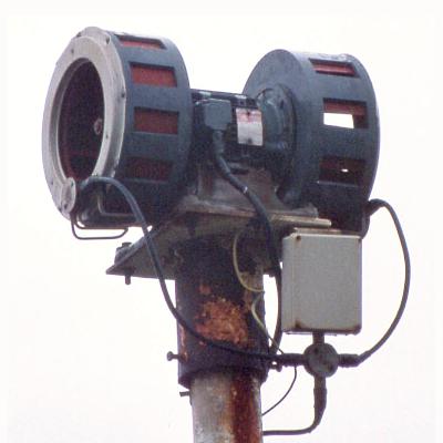
UK Air Raid Siren
Patrick Bean sent me this nice detailed picture of a siren. If you look carefully, two cables come up the pole. One cable connects directly into the siren body. This is the 3-Phase A.C. supply to the motor. The other goes to the 4 way junction box under the grey thermostat box. At the 3 and 9 O'clock position, wires come out to the fan units and go into another junction box where two 'Pyro' type of copper clad heater wires come out. Each fan assembly has a 1 kilowatt heating element to prevent it icing up in the British weather.
Pole Mounted Sirens
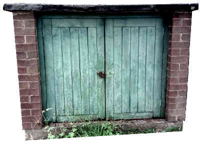
It was standard practice to locate the siren on the roof of a tall building but if suitable premises didn't exist the siren could be pole mounted and the control equipment housed in a street cabinet.
The Mounting of Sirens$
The first three images in the gallery show, firstly an unusual roof mounting in Sale, Greater Manchester. Next - A double wooden pole mounting, guyed for stability. The siren was attached to the lower set of girders, similar to the next image of the Winterton-on-Sea flood siren. Example of a locally constructed table, now restored. Used when mounting on the roof of a building, lifting the siren above the obstruction of a parapet. Three images taken in London during 2012. A brick built standard design of street cabinet, West Mids. Sirens mounted on a single pole, are bolted to the pole cap shown in the gallery.
Fire Sirens
In rural areas Fire Stations are often manned by part time personnel. In the days before personal pagers, retained firemen had a bell inside their house. When away from the bell at home, a siren at the firestation would sound to tell them to make their way to man the fire appliance. This siren which usually was mounted on the drill tower served a dual purpose and could be used for Civil Defence purposes by operating a switch at the fire station.
Once alerting pagers were introduced during the seventies, the fire sirens were kept in situ for Civil Defence only.
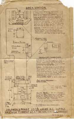
Siren Station Planning Document
The Home Office used a standard arrangement for the siren station as detailed in this sheet kindly provided by Russell Barnes. This planning guide shows the sizes and weights of the various component parts making up a complete station. The siren controls were located on the switch panel described in the next sub-topic.
Siren Station
If the siren was mounted on a building, the siren switch panel was often located close to the point where the electricity supply entered the building housing. Its supply was taken from the non-metered side of the incoming mains. A pole mounted siren would have its switch panel in a nearby cabinet. These have variations from the standard siren station pattern, such as the provision of a heater to stop moisture buildup.
Electrical Operation of the Siren Motor
This simplified block diagram shows how the remote siren control signal from the GPO/BT receiver is routed via the autowailer to the coil of the power relay (contactor) to switch on the 3-Phase supply. If the local autowailer is operated, supply from the remote control signal relay is disconnected so it cannot interfere with local signals and the autowailer interrupter is connected to the contactor. The contactor is required as the low power control signals can't directly operate the powerful siren motor.
Simplified Wiring Diagram3-Phase Mains Contactor
The contactor relay, consists of an mains operated electromagnet that attracts an armature carrying four moving contacts. When mains energises the coil the four moving contacts touch the four fixed contacts and complete four high power electrical circuits. Only three of these are used to connect the three phase supply to the siren motor. There is no neutral supply to the siren motor.
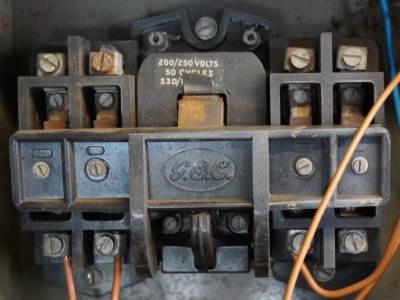
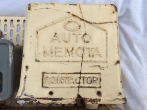
Auto Memota Contactor
This older 'Auto Memota' contactor, found on the former WW2 panels has only three switched poles. In the gallery front view, the electromagnet is underneath the fixed contacts and attracts the spring loaded armature down towards it, making three heavy duty contacts. The two connections to the electromagnet's coil are at the front of the picture.
$
Single Phase Sirens
Domestic premises are normally supplied with a single phase mains electricity supply. In industrial premises, their higher power consumption is met by a three phase supply. High power industrial motors are usually designed for three phase operation, and the siren is no exception but single phase models are known. One single phase version is shown in the Castle Castings gallery.
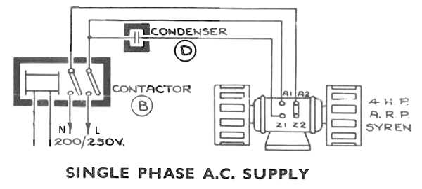
Norman Langridge, kindly offered me this explanation about the operation of single phase induction motors. Referring to this diagram in the Gents' Pamphlet below:
Simplified Wiring Diagram
The starter winding is the one marked Z and is made slightly out of phase with the A winding by connecting condenser 'D' in the live wire to give the motor an initial rotating field. Once the motor is up to or nearly up to full speed, a switch (normally a centrifugal type) inside the motor disconnects the Z winding supply. Note: Condenser is the old terminology for Capacitor.
And further explains the arrangement for 3-Phase motors, sirens in particular.
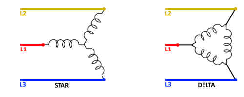
Three phase motors can be started on either a Star or Delta connection. Star has all three windings connected as a common point with the power from each phase connected to their ends so the voltage between any two phases goes through two windings of the motor. This enables a 'soft' start at (relative) low current. Once the motor is getting up to speed a special switching gear can change the connections to Delta which puts the supply of 415 volts across just one winding, each winding being connected end on to the next. If the motor is not excessively large you can start motors on this Delta arrangement and thus cut out the requirements for special starting gear. Initial amperage will be higher, but usually acceptable. Sirens for 3 phase always were started in Delta as this minimises anything that can go wrong and gives a quick run up to speed, but at the expense of a fairly heavy initial start up current. This was necessary in order to recover quickly from the low point of the Wail. Mine takes only 7 amps to run, but needs a 32amp circuit to start.
Star and Delta Motor Configuration
Siren Switch Panel
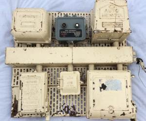
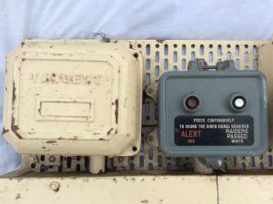
Older Switch Panel
This older style switch panel dates from WWII predates the standard Home Office panels. Its original WWII paddle auto wailer has been replaced by a push button type. The push buttons, acting as a "Dead Man's Handle" prevents the siren being left running, which could happen with the older paddle type.
$
The final image in the gallery, is an original WWII paddle type control box taken from a 1940 public information film although out of context here it serves as a comparison against the various push button operated controllers.
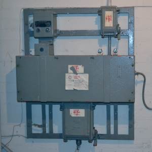
Siren Switch Panel No.1
This is the first of a number of standard Home Office designs of switch panels used on UK Air raid sirens as well as those for firemen's callout, before the advent of personal alerter paging units.
Siren Switch Panel No.1$
The gallery cover image and the first image in the gallery show the Switch Panel No.1 as issued. Over the years some panels have been modified. Images 3 to 5 show a Switch Panel No.1 modified by the addition of a thermal cutout in the siren motor power supply. A locking siren test switch to replace the local autowailer, thereby preventing unauthorised personnel sounding the siren out of curiosity or for a prank.
A two pole isolator switch added into the supply to the BT remote control unit. Before these improvements, when I maintained the WB600, in the seventies, it was necessary to locate and remove the 'PO' fuse, but this left the Neutral wire still connected which presented a shock hazard under fault conditions.
When the WB1400 replaced the WB600, the Carrier Receiver was fitted with a plug allowing it to be totally isolated for maintenance purposes.
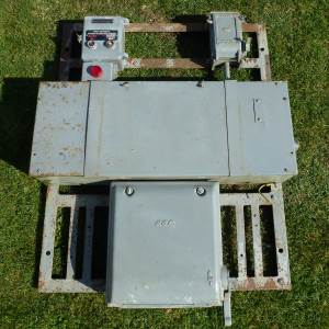
Siren Switch Panel No.3
This panel is designed to work with 240-0-240 volt, 3-Wire single phase, type of mains electricity supply mainly found in rural areas. Paul Lawrence who kindly supplied the photographs, says it was recovered from a town location where one might expect a normal 3-Phase supply. Power distribution company officials have confirmed that in Hastings town, there is a 240-0-240 supply area.
Switch Panel No.3$
The panel uses a 480 / 500 volt single phase siren fed from two anti-phase live wires in a single phase. This type of supply provides 240 volts from each live wire to neutral, and double that across the two live wires. Within the panel, an isolation transformer provides a 240 volt feed to the G.P.O. Equipment and Autowailer, providing them with an earthed neutral independent of the incoming mains neutral, which could rise above earth under fault conditions or a badly balanced set of 2-Wire loads.
The last image in the gallery shows the type of overhead feed this panel was designed to use. This is a rural 240-0-240 volt supply, as lower down the pole are two fuses. The Neutral is earthed and there is a separate earth to the 11 kV insulator support frame. There are two feeds from this transformer, a standard single phase supply on two wires and a three wire 240-0-240 supply in the other direction.
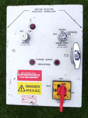
Later Design of Panel with Key Switch Controls in Lieu of an Autowailer
Later Design$
This later version of switch panel has no provision for an autowailer but the siren can still be tested with a key locked switch. There is a similar switch to apply power to the siren heaters. The panel has a Niphan socket for the Receiver Signalling WB1400 for Civil Defence remote control. Provision is also made within the panel to add an additional flood warning receiver, a blanked off hole is provided for another Niphan socket on the opposite side of the box.
Local Siren Control - The Autowailer
Local control of the siren at the siren switch panel can be performed by operating the auto wailer mounted on the panel. The control signals are at mains voltage but with only a low current rating, they are unable to directly feed the powerful siren motor, instead they operate a three phase power relay, known as a contactor.
All the single unit autowailer types retain the same five wiring connections. The two part, earliest design of auto-wailer has some additional connections between the two units.
Mains Input: Phase (Live)
Mains Input: Neutral
Mains Earth
Remote Control Input: GPO (from the GPO/BT apparatus)
Signal Output: Coil (the contactor operating coil)
When the auto wailer is idle, the remote control input from the GPO/BT apparatus is connected through to the signal output, Coil connection.
The remote signal does not operate the local auto wailer. Instead, the siren contactor timings are generated by the remote control equipment at the police station, either from a "master" autowailer in the case of System E, or electronically by the Carrier Control Point (WB600 / WB1400). All sirens activated by remote control, operate in phase, so their sound all rise and fall together.
Operation of either push-button on the local auto wailer disconnects the remote control signal so it can't interfere with local operation.
The various styles of autowailer are displayed here in chronological order.
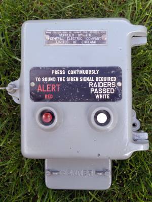
Older Style of Autowailer Box and Switch Unit
Two Part Auto Wailer
A two button device, the siren will only sound the signal as long as the operator holds their finger on the button. The button box is connected to an associated Tangent autowailer. Gent & Co, Leicester produced electrical equipment badged as 'Tangent' probably best known for bells and clocks but there were a wide variety of products including the Siren No.1/L.
$
This type of wailer appears to have been used to replace the original horizontal paddle type wailer when upgrading a WWII siren station for Cold War use.
The Venner Autowailer
Venner Autowailer
Venner AMF, manufactured clocks and time switches until it ceased trading in the mid-Seventies. Perhaps best known for their street lighting clocks in the days before photo-cell control units were developed. This device also required the operator to hold one of the signal buttons depressed to sound the siren. The signal duration is 1 minute which is a long time to have to press a button.
$
In the photo gallery, we can see the internal workings of the auto wailer. The mechanism is covered in brown paxolin insulation to prevent accidental touching of the parts operating at mains voltage. The front cover buttons have projections that protrude through the paxolin cover to operate the electric switches in the non removable part of the wailer. The 'Raiders Passed' switch applies continuous mains voltage to the siren contactor. The 'Alert' switch applies mains voltage to the timing device, the small motor revolves the cam once every 24 Seconds, causing the cam follower to make and break the contacts sending mains voltage to the siren contactor, 5 seconds on, 3 seconds off.
The timing device may be removed for maintenance as shown in the gallery, on the rear are 5 pins to make the electrical connections. In the photo with the paxolin cover removed, the timing cam can be seen and to its right, 'H M S' is stamped on the frame, 24 next to 'S' is the revolution period of the motor.
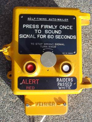
Self Timing Autowailer
This is the Self Timing Auto Wailer: Home Office type 100. This has two buttons and a reset knob to stop the siren before the 60 second time period expired. (Gallery courtesy of Phillip Hallam)
Type 100, Self Timing Autowailer$
Whereas the earlier Grey versions required the operator to hold their finger continually on the button, this needs just a quick push of a button. The gallery shows an internal view with a 3 armed bracket to lock the signal until the top arm is either reset by a peg on a rotating wheel or the arm attached to the door resets it manually. The duration of the signal is normally sixty seconds but two other holes allow the peg to be moved to a 40 S or 48 S duration.
Electrically it is fully compatible with the earlier versions. Like its predecessor the attack timing is 5 seconds power on, 3 seconds off.
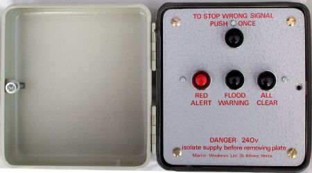
Martin-Woolman Ltd, Electronic Autowailer
Electronic Autowailer
The box has a screwed on hinged cover. The buttons allow local control of the siren and differs from the mechanical type, in that it can also sound a flood warning. The local control box illustrated here with it cover open, has four buttons, the top most is the 'Stop' button. Front from left to right 'Red Alert', 'Flood Warning' and 'All Clear'.
$
This control box, like the earlier mechanical models generates an attack timing is 5 seconds power on, 3 seconds off. Both the attack and all-clear signals last for one minute. The flood signal is 29.5 seconds on and 15.5 seconds off. The internal view of the control box kindly supplied by N.C.Langridge, shows the rear of the board containing two relays controlled by a series of integrated circuits. This box provides the same five external wiring connections and therefore is a drop-in replacement for the earlier mechanical autowailer.
Remote Air Raid Siren Activation
The first GPO control system for remote activation of air raid sirens was developed during World War Two. It provided a means of extending a signal from a home office provided timing device, the auto-wailer situated in a police station, to multiple remote siren stations. A fuller description of these earlier systems are given on the page Chapter35 Pre-Carrier Systems, Remote Control of Sirens from the Chapter Index.
During the early nineteen-sixties, the early warning system utilising a carrier transmitted over normal telephone lines, comprised of the WB400 for speech broadcast and WB600 remote siren activation, replacing all the earlier systems. The HANDEL Carrier Control Point, usually located in a major police station, generated the timing of the siren signals electronically.
During the mid nineteen-eighties the earlier carrier system was replaced by the WB1400 which remained in operation until 1992 when the changing political situation in the Soviet Union rendered a U.K. nuclear warning system unnecessary and it was dismantled.
The remote control attack signal has an equal duration of 4 / 4 seconds ON and OFF, whereas the autowailer produces 5 / 3 seconds ON and OFF. Please get in touch via my home page if you know the reason for this difference.
WB600 and WB1400 Signal Timings
Warning Type
Siren motor power duration
Attack Warning Red
4 seconds ON, 4 seconds OFF; for 1 minute
All Clear
Continuous for 1 minute
Flood Warning
32 seconds ON, 16 seconds OFF; 6 times
Both the WB600 attack warning and WB601 flood warning and their combined replacement, the WB1400 generated siren control signals with the durations shown in this table. Early auto wailers, used for local siren control generated similar signals but their duration was determined by how long the operator kept their finger on the button.
The carrier systems WB400, WB600 and WB1400: giving the police full remote control of the power sirens are fully described on their own series of chapters 10 - 16, accessed from the Chapter Menu, grouped under the section HANDEL: Attack and Fallout Warning
Remote Control of Siren
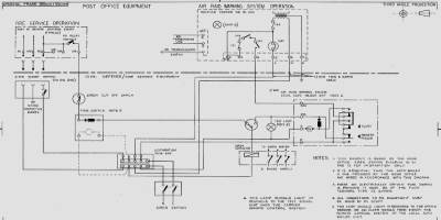
Wiring WB600 to Siren
The Post Office drawing shows the connections of the WB600 Siren control receiver unit to the Home Office wiring at the siren point. The wiring of the switch panel at this date (1962) matches the diagram on the switch panel fusebox door, Photograph No.4 in the Switch Panel No.1 gallery in the topic above.
I don't have an equivalent drawing for the Receiver Signalling WB1400 connection to this Siren Switch Panel No.1, however the WB1400 signalling receiver maintains the same four connections into the panel as the previous WB600 receiver, but instead of being hard wired, the connections are made via a 4-way Niphan plug.
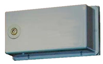
WB600 Carrier Receiver
The original WB600 receiver was mounted on a backplate with lift out hinges at one end, and held in place by small screws, which can be seen in the enlarged photograph from the archives.
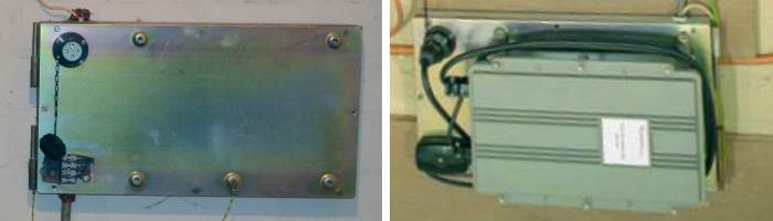
Kit 448A and WB1400 Signalling Receiver
When the WB1400 signalling receiver replaced the WB600 in the mid-eighties, the original back plate was retained and modified with the addition of a Kit 448A. This screwed on to the backplate using the holes that retained the old receiver in the closed position. The Kit448A is a flat plate with pre-drilled and tapped holes for mounting the receiver. It has a 4 pin Niphan socket to accommodate the plug on the receiver. This carries the AC mains supply to the receiver and returns the switched contactor signal output. A connection block on the bottom left terminates the incoming telephone line into the receiver.
On the rear of the Kit448A a short length of wire connects from the terminal block to the original connection block in the backplate used by the previous receiver. Similarly a short length of 4 wire mains cable, preterminated on the rear of the Niphan socket connects to the backplate's original AC mains connection block.
Should the receiver become faulty, it can simply be replaced by unplugging the Niphan and disconnecting the receiver cable carrying the telephone line from the terminal block. There is no need to remove the Kit448 or disturb any of the permanent wiring.
For new WB1400 installations, rather than converted WB600 sites, the Receiver Signalling is screwed directly to the wall or a wooden wall board.
 This page is Copyright © RINGBELL.CO.UK, under a


