Declassified Home Office files reveal a network of resilient cable routes the length and breath of the U.K. with not only underground cables but underground amplifiers and terminal equipment.
Carrier Telephony in the UK
By the sixties the long distance cable network contained many carrier cables, mostly between the major cities but others routed to avoid the centres of population that might be a target in a nuclear war. When introduced in the nineteen thirties, the carrier system allowed 12 separate circuits to be carried on two pairs of wires, one pair in the 'Go' direction and the other pair in the 'Return' direction. Usually all the 'Go' pairs were in one cable and all the 'Return' in a second parallel cable to avoid interference between the two directions. Cables working at carrier frequencies exhibit greater losses than those working in the audio frequency band and required amplifiers every 30 miles.
Further enhancements post WWII allowed two groups of 12 circuits per pair in each direction, thereby doubling the capacity to 24 circuits. With 24 pairs in each of the 'Go' and 'Return' cables, this offered a maximum capacity of 576 circuits. Cable losses at the higher frequencies needed for 24 channel working required amplifiers at approximately 15 mile intervals. Some of the existing repeater stations were retained, but numerous new repeater stations were built to achieve the 15 mile intervals between amplifiers. A standard building design simplified the process. This was known as the "R3 Type" of repeater station building.
A detailed explanation of speech multiplexing used to get 24 circuits per pair on carrier cables is provided in a separate chapter on this website. Found in the Miscellaneous Topics part of the Chapter Menu.
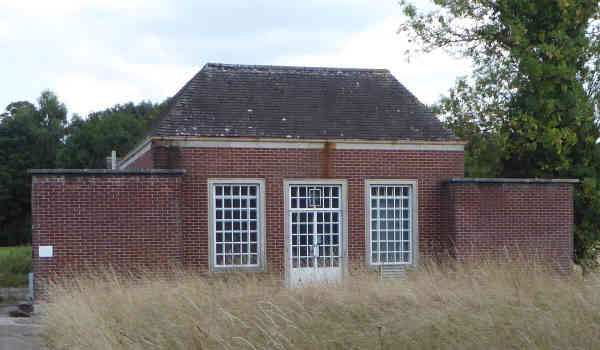
R3 Standard Repeater Station Building
In the days before semiconductors, sizable buildings were required to accommodate the bulky thermionic valve amplifiers, one per cable pair, 48 in total for the usual 24 pair cable type. As well as the amplifiers themselves, a large power plant and standby generator was required to supply the considerable amount of energy consumed by the thermionic valve heaters and high voltage anode supply.
Carrier Amplifiers
At the Terminal Repeater Station, 24 individual audio circuits are multiplexed and sent along a 'Go' pair and demultiplexed from the 'Return' pair. The carrier cable has either 14 or 24 pairs of conductors, each 1.27 mm in diameter, the overall size of the cable is approx. 34 mm in diameter. If fully equipped, a pair of 14 pair cables has a capacity of 336 circuits, while a pair of 24 pair cables has an ultimate capacity of 576 circuits. There will be a terminal station at the other end too, but not shown below.
Simplified Diagram
At intermediate repeater stations, the incoming carrier on each pair is amplified and sent out over the next section of cable. An intermediate repeater station may have more than one cable route passing through it. In that case, not shown in the simplified diagram is the flexibility to break off one or more pairs onto another cable for a different destination.
$
Overview of All Underground
These repeater stations were vulnerable to blast damage, so in order to protect the circuits in the core infrastructure of the Emergency Manual Switching System (EMSS), a scheme known as 'All Underground' was developed. In contrast to the normal carrier systems employing thermionic valves, this network used newly developed Transistorised 24-Channel Carrier Equipment in protected basements at terminal stations and transistorised amplifiers at the repeater stations.
All Underground Route : Superimposed over Tier 1 & 2 EMSS Sites
I have redrawn the map above, found in Home Office file HO 322/824 in the National Archives at Kew, and adding context by showing the location of EMSS Tier 1 & 2 node sites. Being 'Top Secret', the Central Government War HQ at Corsham was not shown even though it was part of the 'All Underground' network.
Intermediate Repeater Stations
The 'All Underground' network intercepted two pairs of wires in each carrier cable before they entered the repeater station and used transistorised amplifiers fitted inside robust steel cases located in a jointing chamber in the grounds of the repeater station. The two 'Go' amplifiers were housed in one case and the two 'Return' amplifiers in a second case. Another jointing chamber housed two sets of batteries, one feeding each amplifier case.
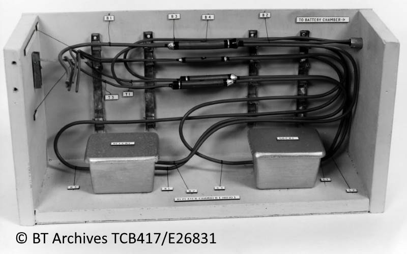
The remaining 22 pairs (3 to 24) continued to be amplified inside the repeater station with thermionic valve amplifiers. BT Archives contain a photograph of model of the jointing chamber containing the amplifier cases. At the terminal stations, the two pairs of the 'All Underground' network were terminated on self contained transistorised multiplex equipment, housed in the basement. The remaining 22 'normal' circuits continued upstairs to the repeater station in the telephone exchange building.
Repeater Chamber : Mock Up of Layout
The two batteries consisted of 8 lead-acid cells each, providing 16 volts to power the amplifiers. These were charged from a 18.1 volt mains power unit (Power Plant 129) located in an underground room in the repeater station. The amplifiers consume 460 mA from each battery. Battery capacity of 141 Ah giving about 300 hours of reserve power.
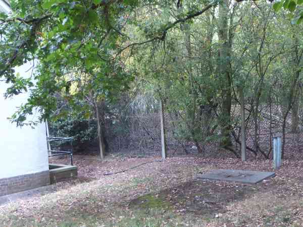
The jointing chamber containing the two batteries required ventilation to avoid the build-up of hydrogen gas and acid vapour. The ventilation was afforded by two vent pipes fitted with cowls facing in opposite directions. The specification calls for the battery chamber to be sited within 3 feet of a property boundary and the lid raised 1.5 inches above the ground. When passing I have photographed some sites and with the help of Google Street view too, these long redundant pipes and manholes still can be seen at some repeater stations. All conform to the basic pattern of vented battery manholes and various sizes of amplifier manholes.
Redundant ′All Underground′ facilities : Gallery
The final image in the gallery shows the extent of the network needed to support the EMSS. Each red spot represents a repeater station or exchange. All of the repeater stations and some exchanges had amplifiers in the manholes outside, only at terminal or intermediate exchanges did the circuits go inside the building to apparatus in protected rooms in the basement.
$
Digital Upgrade circa 1986
In its basic form, the 'All Underground' network provided up to 48 individual circuits between terminal points using two pairs in a multi-pair cable. These were analogue speech circuits carried over analogue multiplex.
During the eighties, the sixties analogue multiplex equipment was upgraded to digital multiplex. Now each pair of go and return wires could carry 120 speech channels instead of the previous 24 on the analogue multiplex. The cable interface equipment is known as 'Equipment Digital Line 8A' (EDL8A) each providing four 2-Megabit ports that may be connected to standard 30 Channel digital multiplex equipment or a 2-Megabit port on a digital telephone exchange. The part of the network descending south from Worcester was made digital by 1-September-1986. The Peterborough section northward to York, target completion date was 17-October-1986.
Once digital, the 2 pairs in the 24 pair cables dedicated to 'All Underground' and their associated terminal and amplifier points were referred to as a 'Supplementary' [sic] to the Public Switched Telephone Network and given the code 'S8S'. BT Telecom Instruction 'A3 H3501' gives planning guidance for both Main and Supplementary digital line systems, without mentioning their purpose. The S8S could carry 240 circuits compared with 48 in the analogue equivalent.
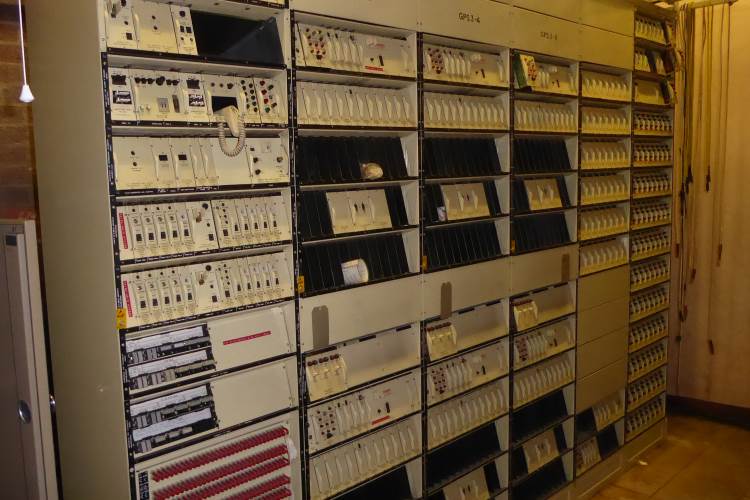
The photograph gallery below shows the digital multiplex equipment housed in a copper clad room in the basement adjoining the EMSS switchboard. The four 2 Mbit outputs from the S8S are fed into 30 Ch. PCM multiplex that breaks down each 2-Megabit digital signal into 30 analogue speech channels connected to the EMSS switchboard.
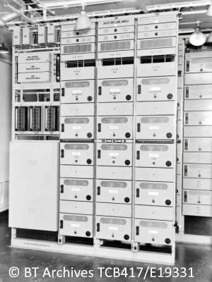
Digital Transmission Equipment EDL8A for All Underground Network
Similar EDL8A racks can be seen in the Central Government War HQ at Corsham. This secret location was not marked on the map at the top of this page however its identifying Q-Code of QQCF can be seen at Worcester and the photographs of the Corsham bunker's racks.
The digital transmission network required amplification at shorter distances. Instead of using batteries in manholes, the amplifiers were powered from terminal stations by feeding the power down the same wires that carry the digital signal. The terminal stations operated at 50 volts, making use of the 50 volt reserve batteries for the EMSS and the standby generators at those locations.
Signal regeneration was required at approximately 3 Km intervals, the regenerators being located in two robust cases, one for each direction. At power feed stations a third case held maintenance spares. The two or three robust cases (Case, Repeater Equipment No.1A) are sited in a convenient manhole as in normal practice.
$
Closure of All Underground
Cabinet Papers from 10th June 1993, held in the National Archives at Kew, give a closure date. This decision was prompted by the Government Review of Emergency Communications (GREC) report. The report was further scrutinised by the Post Review Working Party (PRWP).
CAB 134 / 5766 extract . . . [12] Two separate, BT provided, EMSS transmission systems, the 'Backbone Radio' (BBR) and 'All Underground' (AUG) schemes, had also been reviewed by GREC. In accordance with its recommendations . . . . the obsolescent cable-based AUG was closed in January 1992. The GREC recommendation that the AUG pathways could, if refurbished with optical fibre, provide resilience to EMP for other emergency communications networks including the enhanced ECN, had been rejected by the PRWP as too costly to implement.
 The Images from BT Archives are Copyright BT Heritage, licensed under a


