Speech multiplex allows a number of speech channels to be carried over the same physical circuit. This is a description of the analogue multiplex that was current during the cold war era and is known as Frequency Division Multiplex (FDM).
Background
The Human Voice
Our voice consists of a spectrum of sound frequencies from a few hertz to many tens of kilohertz. The Hertz (Hz) is the unit of measurement for the number of times per second, an object vibrates or electric signal oscillates. However the human brain can still decipher words and music even when a large part of this spectrum is missing. Compact Disk (CD) quality music restricts the highest frequency to around 24 kilohertz and we find this perfectly acceptable. The same CD frequency range is used when encoding .MP3 files. The telephone network makes use of this human ability, by further restricting the bandwidth from 300 to 3400 Hertz. Whilst this range is not acceptable for music an individual's voice can still be recognised. Although most of the energy is contained in the lower frequencies, it is the higher frequencies that convey the intelligibility.
Bandwidth of Copper Wires
Pairs of copper wires used to carry telephone calls have a much greater bandwidth than is necessary to carry human speech. As the length of wires increases the available bandwidth decreases due to absorption of the higher frequencies. The line absorption losses may be overcome by amplifying the signal at regular intervals, there is a trade off between usable bandwidth and the cost of amplifying the line, which is why it was only economical for long distance circuits. The upper limit for telephony was set at 3400 Hertz on unamplified customers lines.
Bandwidth of Radio Transmitters
Radio transmitters can be designed for any bandwidth required. There are a number of factors influencing the choice of bandwidth mostly related to the operating frequency and channel spacing. The analogue Stereo music standard for Europe and the UK used from the nineteen sixties onwards has transmitters spaced at 100 kilohertz intervals. Digital radio known as DAB is very different and not explained here. Radio transmitters for single analogue speech channels restrict their bandwidth to a similar value to that used over copper wires. Many comply with the CCITT standard originally set for landline communications. By designing a transmitter with a wider bandwidth it is possible to send anything from two to many thousands of circuits over a single radio path.
Utilising the Bandwidth
The extra bandwidth on landlines was used in the Cold War era to deliver signals to WB400 & WB1400 early warning receivers. Nowadays broadband internet (ADSL) delivered over home telephone lines (but not Cable TV) uses that bandwidth to carry the modem signals into the house.
The extra bandwidth available on copper wires and radio circuits may be exploited using a Frequency Division Multiplex to send more than one speech channel down a single circuit. The actual number of channels combined together depends on a number of factors but usually how many speech circuits are currently or likely to be required in the future. The multiplex techniques vary depending on the number of circuits to be carried.
Frequency Changing Process
Key to analogue speech multiplex devices is the frequency translator. This is a simple mixer having two inputs and one output. If for example a frequency of 5kHz is fed into one input and 70 kHz into the other, then the output consists of the two input frequencies and the sum of the two; 75 kHz and the difference 65 kHz.
By employing a balanced mixer, the two input frequencies can be eliminated from the output leaving only the sum and difference frequencies. When one of those inputs is speech and the second input has a higher frequency referred to as the carrier, the output consists of a range of frequencies in two blocks offset either side of the carrier frequency. The lower sideband block is inverted compared to the speech input and the upper sideband block remains erect. To achieve a frequency change, one of the two frequency blocks is removed and the other passes to the next stage.
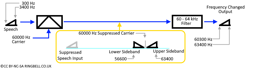
To illustrate this process, the speech whose frequency is to be changed is represented on diagrams as a sloping triangle. The height of the line increases with increasing frequency and does not represent the energy at that frequency. This allows the channel combining and inversion processes to be shown in a meaningful way.
Frequency Changing
In this diagram, the balanced mixer suppresses the audio input and the carrier and outputs two sidebands. The lower sideband ranges from 56600 to 59700 Hz and the upper sideband 60300 to 63400 Hz. The upper sideband block is allowed through the filter and the lower sideband rejected, but equally a 56-60 kHz filter would allow the lower sideband to be selected. Lower sideband selection is used for down conversion where the output is below the carrier frequency.
Two Channel Multiplex
The two channel multiplex finds applications in both landline and radio communications and is usually known as 1+1 as one circuit remains as a speech circuit and the other circuit is shifted in frequency so the two do not interfere. In the UK, the dreaded shared service (party line) was replaced with the WB900, which is essentially an analogue two channel multiplex allowing two customers on one pair of wires to the exchange. Two channel multiplex over radio were deployed during the cold war in the MOULD network and in the second generation ECN on some RN2 circuits.
MOULD - Pye - Radio Terminal Unit RTU 1+1
Where it is necessary to feed two or more speech circuits between hilltop sites, the use of a RTU 1+1 at each end allows the saving of two transmitters and two receivers and their associated aerials for each pair of circuits.
The RTU provided two circuits with a frequency response of 300 to 3000 Hz over a single 9kHz bandwidth radio circuit. This frequency response while suitable for the MOULD application didn't meet the CCITT bandwidth requirements of 300 to 3400 Hz needed for telephone circuits and was not used in the RN2 part of the ECN.
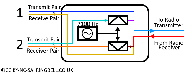
The first circuit is filtered by a low pass filter to remove any frequencies that might interfere with the other circuit and sent as plain audio. The second speech circuit is mixed with a 7100 Hz carrier, the lower sideband in the range 4100 to 6800 Hz is allowed to pass through a filter and combined with the first circuit and sent to the radio link transmitter. The transmitter input contains frequencies in the range 300 to 6800 Hz
The output from the radio link receiver is divided in the RTU into two paths. The first path is filtered to remove frequencies above 3000 Hz to prevent interference from the second circuit and becomes the received audio for the first circuit. The second path is filtered to reject everything outside the 4100 to 6800 Hz band, its then mixed with the 7100 Hz carrier and routed via a 3000 Hz low pass filter to recover the speech on the second circuit.
Simplified RTU 1 + 1 Block Diagram
Should anyone listen with a scanning receiver to a 1+1 multiplexed radio circuit, they would hear the normal speech on circuit one and a squeaky high pitched sound when circuit two was in use. A RTU is required at both ends of the radio path.
RN2 - Pye DLM1
Operation of the DLM1 is very similar to that of the RTU 1+1 but it provides two CCITT compliant 300 to 3400 Hz speech circuits. The second circuit is frequency changed using an 8000 Hz carrier to produce a lower sideband in the range 4600 to 7700 Hz consequently requiring a 15 kHz bandwidth radio path. The DLM1 has a built in signalling interface using E&M over the metallic circuit and 3825 Hz out-of-band tone on the radio circuit. A DLM1 is required at both ends of the radio path, this radio circuit is completely incompatible with the RTU described above.
Low to Medium Capacity Multiplex
The Civilian Cold War communications networks used low capacity multiplex in both the RN1 spine and RN2 branch sections of the ECN network. It also had commercial applications too in the U.K. Gas Council Network, Civil Aviation Authority and National Grid [Electricity Generator / Distributor] very few private companies had sufficient circuit requirements to justify the expense of their own radio multiplex.
The multiplex arrangement explained here is common to most equipment manufacturers but their implementation varies. The multiplexing combines 12 audio circuits in a two stage process into a 'Basic Group' the building block defined by the CCITT. An audio circuit has a frequency response from 300 Hz to 3.4 kHz, signalling may take place at 3825 Hz, requiring a bandwidth of 4 kHz. The twelve audio circuits are frequency changed to produce a Basic Group with a 12 x 4 = 48 kHz bandwidth occupying frequencies between 60 and 108 kHz. If there is need for fewer than 12 circuits, some of the channels can be left unequipped.
A Basic Group can be connected to a radio link in the UHF or microwave bands. Some manufacturers offer products with 24 or 36 circuits, by combining two or three basic groups into one radio link, but due to the bandwidth required these are only carried on Microwave links.
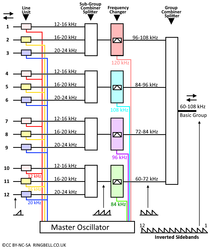
Using a two stage process minimises the number of types of line units, down from 12 to just 3 designs. Circuits 1, 4, 7 & 10 are all the same, similarly for 2, 5, 8 & 11 and 3, 6, 9 & 12. The line card handles the signalling in both directions and converts the circuits transmitted audio by changing its frequency into one of three intermediate frequencies that are mixed with the others in the Sub-Group combiner. The four transmit intermediate frequency Sub-Groups now in the range 12-16 kHz passes into one of four frequency translators. The four outputs are joined together in the Group Combiner to form the Basic Group.
12 Circuit Multiplex
The incoming Basic Group from the receiver feeds into the Group Splitter, where its filtered and sent to one of four frequency translators. The output of the frequency translator, now in the range 12-24 kHz feeds the Sub-Group splitter breaking it into the appropriate frequency range for the line unit. The line unit frequency changes the signal back into the received channel audio.
Creating a Baseband Signal
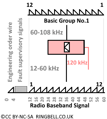
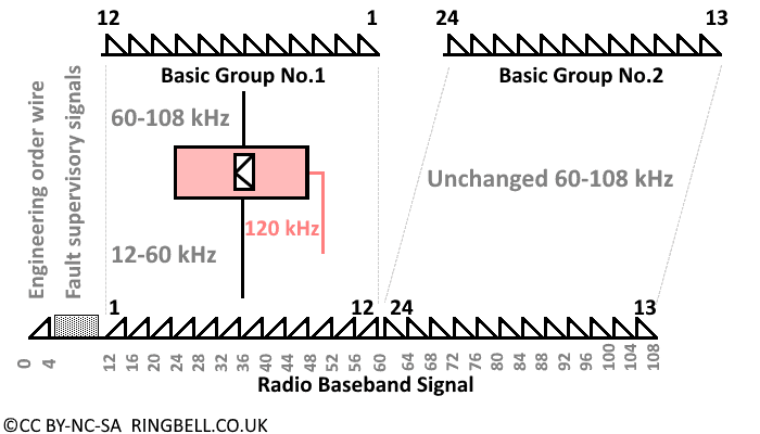
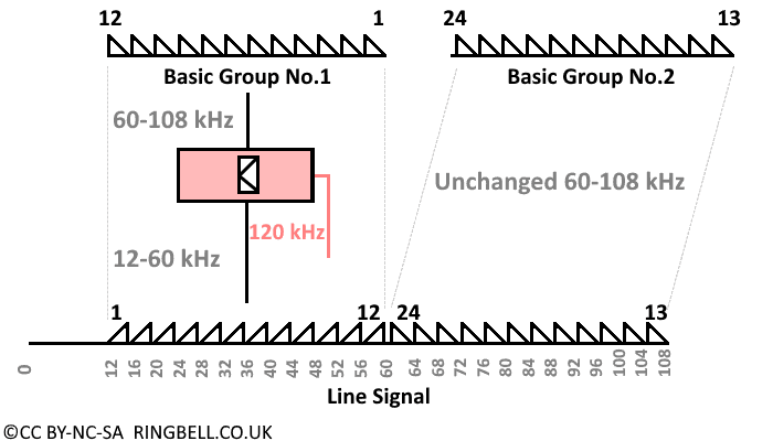
The required bandwidth of a radio transmitter is proportional to the modulating frequency. To minimise the radio bandwidth the Basic Group is frequency changed from 60-108 kHz to a 12-60 kHz baseband signal. As the frequencies below 12 kHz are not required for the 12 circuits, this bandwidth is used to carry an engineer's speaker circuit (commonly known as an 'Order Wire') and supervisory signals to indicate remote fault conditions. The incoming baseband signal 12-60 kHz from the receiver is frequency changed back to the Basic Group frequencies 60-108 kHz to feed the multiplex.
24 Circuit Radio Links
A 24 Channel radio system can be created by using two twelve channel multiplex to provide two Basic Groups. If these are on the same equipment rack, they may share common services such as supervisory alarms and master oscillator. One Basic Group has its frequency changed, then added to the second group to form a 24 channel baseband.
Practical Example
Individual multiplexed circuits are cross connected at radio nodes as required to provide longer distance connections. Smaller capacity Multiplex would typically be used on spurs with the larger sizes providing a spine network. Economics dictates that a non-multiplexed single circuit per radio channel would be used to feed sites requiring only a few links. The diagram below is a hypothetical case to illustrate the principle involved but does not represent any real life example.
Use of Speech Multiplex on Radio Links
Something like this arrangement was used in the ECN radio network spine RN1 and RN2 known also as the 'Highway Network'.
Large Capacity Multiplex
During the Cold War period Public Telecommunications Operators (PTO) throughout the world, which means GPO / PO Telephones / BT in the United Kingdom, conveyed their long distance circuits using Frequency Division Multiplex (FDM). A few larger private companies and nationalised industries such as British Rail had their own networks of hundreds of FDM circuits.
FDM on the scale needed for PTO's requires a different approach to that adopted for lower capacity multiplex. A single stage is used to get from audio to the Basic Group. The group combiner / splitter is cabled to the Group Distribution Frame (GDF) to allow flexibility in connecting the groups to different line systems.
Two Basic groups are required to create a 24 channel line system used on copper pair cable. Five Basic Groups can be further translated into a 60 circuit Super Group. The Super Group is the building block for coaxial cable line systems.
The FDM equipment is usually co-sited with the telephone exchange in a Telephone Repeater Station (TRS) that may also contain amplifiers for the purely audio circuits between exchanges. There may be dozens or perhaps hundreds of Basic Group multiplex in a TRS. A single frequency generator feeds all the multiplex in a TRS.
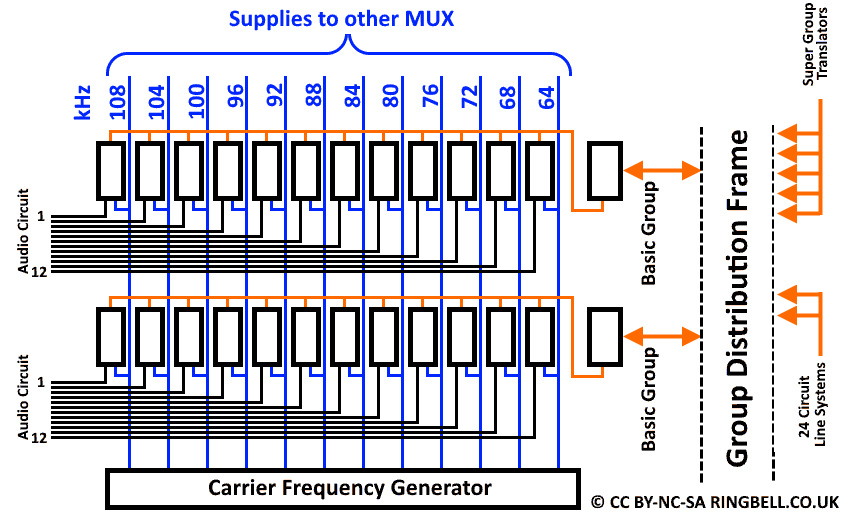
Channel Translation into a Basic Group
Each individual channel card handles both the transmit and receive paths frequency translation. The 12 transmit carriers are combined to form a Basic Group 60-108 kHz, the received Basic Group signal is split 12 ways to feed the line cards which translate the carrier back to audio. Each of the 12 channel cards is supplied with a different modulating frequency, channel 1 being the highest and channel 12 the lowest.
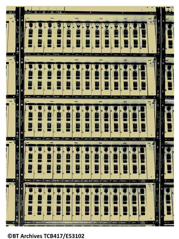
The photo below shows a number of groups multiplex each occupying one shelf with thirteen slide in units. There are twelve channel cards with the group combiner / splitter being the right hand card on each shelf. Its output coaxial leads terminate on a Group Distribution Frame (GDF) or High Frequency Repeater Distribution Frame (HFRDF) allowing flexibility in connecting groups to other hierarchical equipment or line systems.
Equipment Frequency Translation
24 Channel Line System
During the nineteen thirties the British Post Office installed special carrier cables on long distance routes capable of carrying one group of twelve channels. Two separate cables each having 24 pairs of copper wires were laid, each cable carries the signals in opposite directions. In order to utilise the maximum bandwidth with maximum spacing between amplifiers, the group was translated from 60-108 kHz into 12-60 kHz. Later these line systems were upgraded to carry 24 channels per pair of wires by reducing the spacing between amplifiers. The second group was not changed in frequency but added to the first group as shown below.
24 Channel Carrier Cable Line System
24 Channel line systems were particularly important for the 'All Underground' network used to carry calls between 'Emergency Manual Switching System' (EMSS) exchanges. Both these topics have their own webpage accessed via the Chapter Menu. Briefly, two or four of the twenty four pairs were amplified in underground manholes with the remainder amplified as usual inside the repeater station building, allowing the protected circuits to continue to work should the building be destroyed in a wartime emergency.
Super Group Translating Equipment
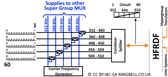
A Super Group consists of 60 circuits in a band ranging from 312-552 kHz constructed from 5 sets of 12 channel Basic Groups and can be seen as the next level of hierarchy. Each group undergoes a frequency translation with five different carrier frequencies. The transmit basic groups are modulated and the lower sideband selected to be combined into a supergroup and received supergroup split into five basic groups.
60 Channel Super Group
The Super Group translator equipment is cabled to the High Frequency Repeater Distribution Frame (HFRDF) which allows flexibility on its inputs and output.
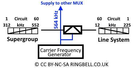
60 Channel Line System
Improved design of carrier cables allowed their use for 60 circuit systems with amplifiers every 19km. The normal supergroup is modulated by 564 kHz and the lower sideband selected to give a line frequency of 12-252 kHz. Like their 24-circuit counterparts, two separate cables carried the transmit and receive signals.
60 Channel Line System Translation
While the majority of 60-circuit cables were used for public telephony, the Woodland exchange in the government bunker at Corsham had a cable route to Bristol and in the mid-sixties two new 14-Pair cables were laid from Woodlands, via Cheltenham, Worcester, Kidderminster to Shrewsbury. This would give an ultimate capacity of 60 x 14 = 840 circuits.
Coaxial Cable Line Systems
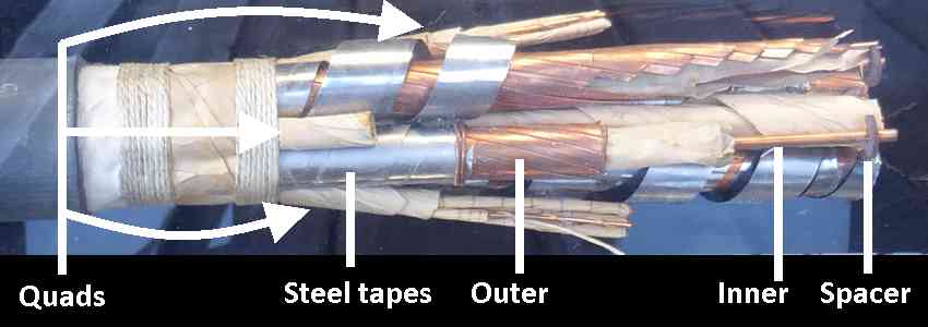
A coaxial cable used by the British Post Office consists of a copper tube containing a smaller solid inner conductor held centrally by plastic spacers. For protection against damage each tube is wrapped in a layer of steel tape. This example in a display case at Avoncroft Museum shows a four tube cable with the gaps filled by quads of conductors wrapped in paper and used to feed power to buried amplifiers and for engineering supervisory circuits.
4-Tube Coaxial Cable
The British Post Office employed coaxial cable systems with various capacities within its network to carry normal telephony, television channels and radar signals. It had no special cold war features but it is included here for completeness as the next FDM tier above carrier cables.
The most common coaxial line system, was the 960 channel / 4 MHz, containing 16 supergroups. Each underwent a frequency change as described in previous topics to produce a line frequency range of 60 - 4028 kHz.
A higher capacity coax line system assembled 15 supergroups (900 circuits) into a hypergroup with a frequency range of 312 - 4028 kHz. Three hypergroups were assembled by leaving the first unchanged, but frequency changing the second with 8432 kHz and filtering the lower sideband 4404 - 8120 kHz and the third frequency changed with 12648 kHz and again filtering the lower sideband 8620 - 12336 kHz. This produces a 2700 channel / 12 MHz line system operating in the range 312 - 12336.
Microwave Systems
Hypergroups of varying sizes can be used to modulate Microwave transmitters that formed part of the British Post Office / BT Microwave Network until it became digital in the nineties. The Microwave Network also carried a large number of television circuits too, forming part of the BBC 1&2 and ITV distribution from studios to main TV transmitters.
By comparison, the Cold War 'Backbone Network' carried no more than 10 supergroups / 600 circuits over the most busy part between Arncliffe Wood and Stokenchurch. The sections between Corby's Crags to Craigowl (Scotland) and Kelvedon Hatch to Fairseat were only equipped for 4 supergroups / 240 circuits. Other sections having 8 equipped supergroups.
The MUX Mountain
The term 'MUX Mountain' is used to deride the analogue Frequency Division Multiplex (FDM) system. Digital communications still requires multiplex but they are far less bulky than the nineteen sixties analogue technology and switching can be carried out directly at high data rates. At each analogue exchange, the higher order long distance circuits had to be demultiplexed to audio and converted from a 4-wire to 2-wire circuit as shown below.
Analogue Multiplexed Telephony Circuits
As speech circuits are bi-directional, in the 'Go' direction a multiplex is required at the A-End and a demultiplex at the B-End, in the 'Return' direction there will also be a multiplexer at the B-End and a corresponding de-multiplexer at the A-End. In the equipment used by the GPO / BT the multiplex and demultiplex were combined within the same slide in unit.
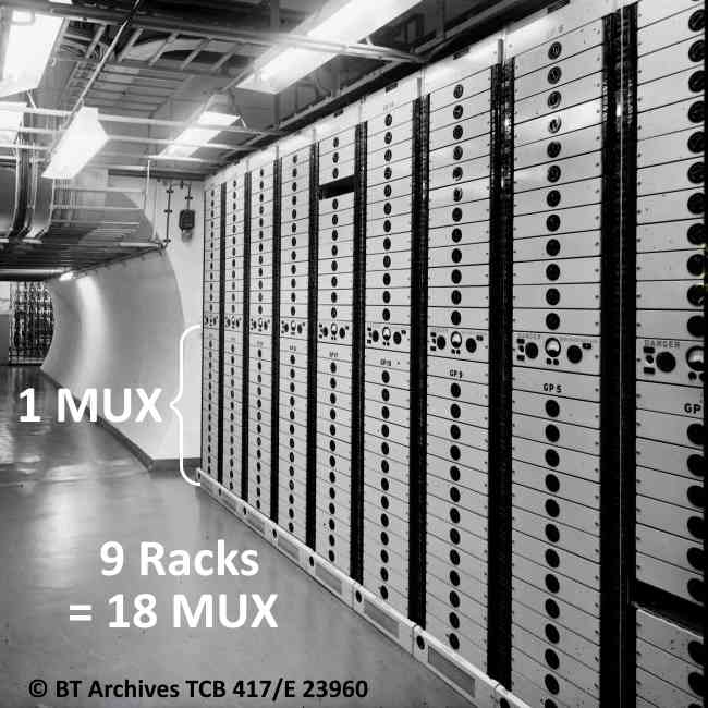
A typical 960 circuit coaxial system requires 80 group multiplex plus 16 supergroup multiplex and 15 supergroup frequency changers at each end of the system. Photographs of the three underground exchanges and hardened repeater stations show huge qualities of racks containing 12-Channel multiplex like this at Birmingham Anchor. Being nineteen fifties technology each rack contained just two group multiplex.
 This page is Copyright © RINGBELL.CO.UK, under a